SNOU206 October   2024 LMG2640


  1.   1
  2.   Description
  3.   Features
  4.   Applications
  5.   5
  6. 1Evaluation Module Overview
    1. 1.1 Introduction
    2. 1.2 Kit Contents
    3. 1.3 Specification
    4. 1.4 Device Information
    5. 1.5 General TI High Voltage Evaluation User Safety Guidelines
      1. 1.5.1 Safety and Precautions
  7. 2Hardware
    1. 2.1 LMG2640EVM-090 Daughter Card
      1. 2.1.1 Test Points
      2. 2.1.2 Integrated Current Sensing
      3. 2.1.3 Enable Pin
      4. 2.1.4 FAULT
      5. 2.1.5 Power Pins
      6. 2.1.6 Heat Sink
    2. 2.2 Motherboard
      1. 2.2.1 Bias Supply
      2. 2.2.2 PWM Input
      3. 2.2.3 Fault Protection
    3. 2.3 Recommended Footprint
    4. 2.4 Test Equipment
    5. 2.5 Test Procedure When Paired With LMG342X-BB-EVM
      1. 2.5.1 Setup
      2. 2.5.2 Start-Up and Operating Procedure
      3. 2.5.3 Test Results
      4. 2.5.4 Shutdown Procedure
      5. 2.5.5 Additional Operating Notes
  8. 3Hardware Design Files
    1. 3.1 LMG2640EVM-090 Schematic
    2. 3.2 Motherboard Schematic
    3. 3.3 PCB Layout
    4. 3.4 Bill of Materials
  9. 4Additional Information
    1. 4.1 Trademarks
  10. 5Related Documentation

Test Results

In this test example, a synchronous boost converter operation is implemented. The input voltage is 200V, and the output voltage is 400V with 50% duty cycle. With the heat-sink-version EVM, the inductor current is triangular and operating in continuous conduction mode (CCM). The peak inductor current is about 5A in this test, and an output power of 800W is achieved. Higher currents and power levels can be tested, and monitoring the device temperature is recommended to avoid thermal shutdown. The waveform for continuous operation is shown in Figure 2-7.

The slew rate is fixed by connecting a 0Ohm resistor between RDRVL and AGND for the low side FET, and connecting a 0Ohm resistor between RDRVH and SW for the high side FET. A turn-on voltage waveform of 100V/ns is observed with this slew rate, and demonstrated on this EVM at 400V. High slew rate enables the lowest switching losses with minimum overlap during hard-switching events, and integrated gate drivers enable minimum voltage overshoot to aid EMI performance when designing.
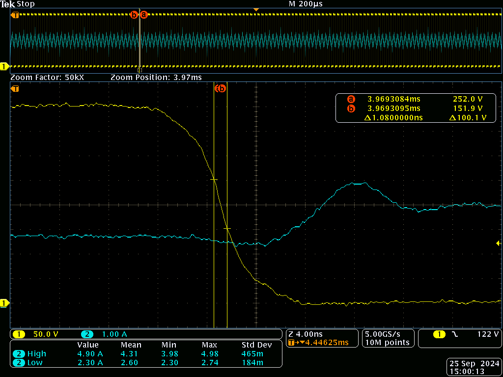
LMG2640EVM-090 100V/ns at
                              400V/2A Figure 2-7 100V/ns at 400V/2A