SNVA012C May 1999 – December 2021 LM2653
2 Evaluation Board Design
The evaluation board is designed to supply 2.5 V at up to 1.5A. The input voltage range is 4 V to 14 V. Components were selected based on the design procedure in the LM2653 1.5A High Efficiency Synchronous Switching Regulator Data Sheet (SNVS050). The feedback resistors can be adjusted to achieve a different output voltage:
Choose 1% resistors between 10 kΩ to 100 kΩ for R1 and R2.
PCB layout is critical to reduce noises and ensure specified performance. For layout guidelines, see the LM2653 1.5A High Efficiency Synchronous Switching Regulator Data Sheet (SNVS050). The artwork for the evaluation board is shown at the end of this application report.
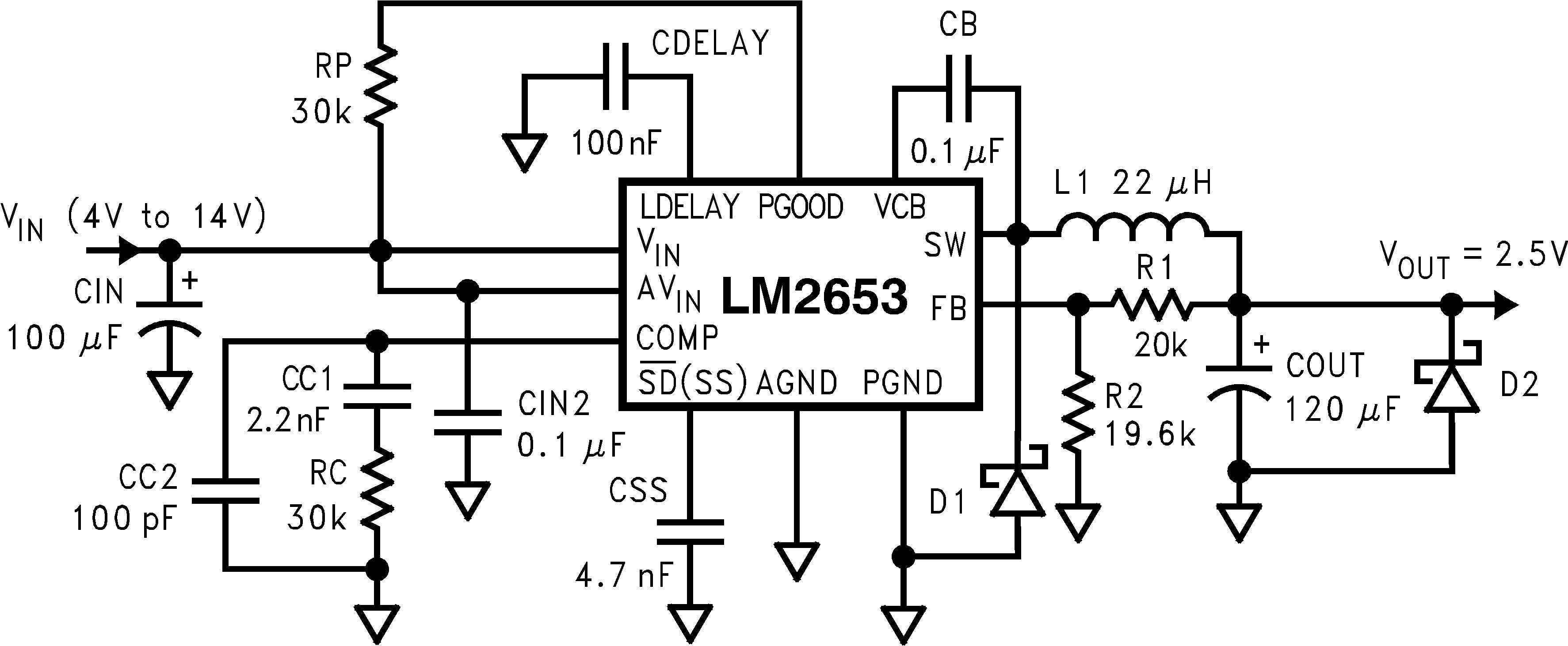
The schematic for the evaluation board is shown in Figure 2-1, and the parts list is given in Table 2-1.
When the undervoltage protection occurs, the output voltage can be pulled below ground as the inductor current is reversed through the synchronous FET. For applications that need to be protected from a negative voltage, a clamping diode D2 is recommended.
The PGOOD flag goes low whenever the overvoltage or undervoltage latch protection is enabled. The overvoltage protection will be enabled immediately when the output voltage exceeds 110% of its nominal. While the undervoltage latch protection will wait for a period of time set by the LDELAY capacitor. If the output voltage is still below 80% of its nominal after this waiting period, the latch protection will be enabled.
 Figure 2-1 LM2653 EVAL Schematic
| Designation | Description |
|---|---|
| L1 | 22 µH, Coilcraft DO3316P-223 |
| CIN (input capacitor) | 100 µF, 16 V, Sprague 594D107X0016D2T |
| CIN2 (input capacitor) | 0.1 µF ceramic capacitor |
| CB (bootstrap capacitor) | 0.1 µF ceramic capacitor |
| CSS (softstart capacitor) | 4.7 nF ceramic capacitor |
| COUT (output capacitor) | 120 µF, 6.3 V, Sprague 594D127X06R3C2T |
| CC1 (compensation) | 2.2 nF ceramic capacitor |
| CC2 (compensation) | 100 pF ceramic capacitor |
| RC (compensation) | 30 kΩ, 5% resistor |
| D1 | 1A Schottky diode, Motorola MBRA130LT3 |
| R1 | 20.0k, 1% resistor |
| R2 | 19.6k, 1% resistor |
| CDELAY | 100 nF ceramic capacitor |
| RP | 50K, 5% resistor |
| D2 | Open |