SNVA057D August 2002 – February 2022 LM2727 , LM2737
6 Layout Optimization
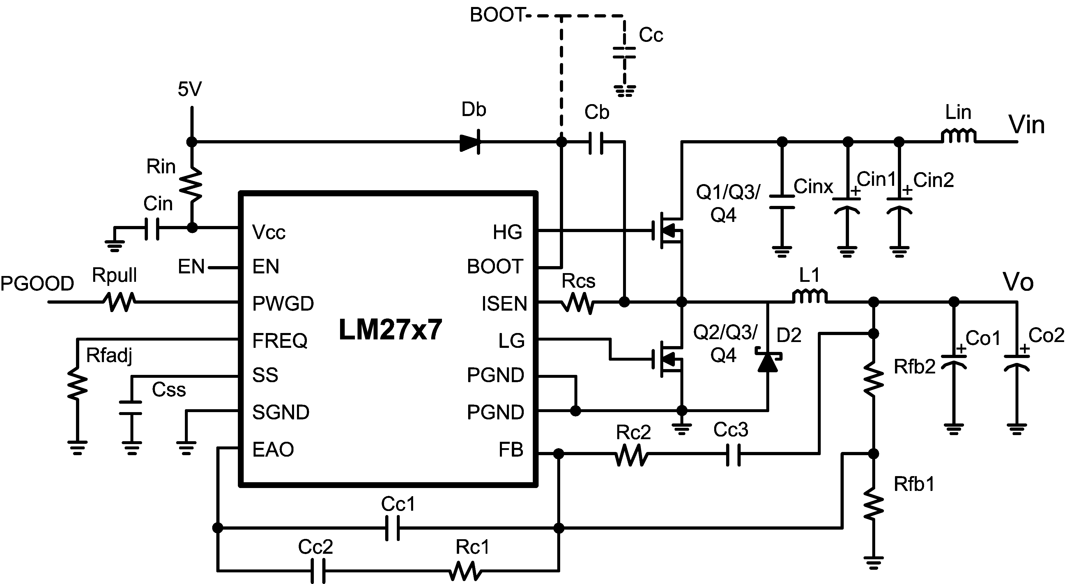
The LM2727 PCB layout could be improved with several techniques used in switching converter design. The traces that run from the HG and LG pins of the IC to the gates of the high-side and low-side MOSFETs should be shorter and thicker, reducing their parasitic inductance and resistance. The mid-frequency decoupling capacitor, CINX, should be placed as close to the pins of the high-side MOSFET as possible. The bulk input capacitors, CIN1 and CIN2, should also be placed close, keeping the loop between the input capacitors and the high-side MOSFET small. Likewise, the Schottky diode D2 should be located as close as possible to the pins of the low-side MOSFET. The local capacitors CIN, CBOOT, and CC (if used) should be close to the pins of the LM2727 IC. These techniques help reduce parasitic inductance throughout the PCB.
 Figure 6-1 Circuit Schematic
| ID | Part Number | Type | Size | Parameters | Qty. | Vendor |
|---|---|---|---|---|---|---|
| U1 | LM2727 | Synchronous Controller | TSSOP-14 | 1 | NSC | |
| Q1 | Si4884DY | N-MOSFET | SOIC-8 | 13.5 mΩ, at 4.5 V, 15.3 nC | 1 | Vishay |
| Q2 | Si4884DY | N-MOSFET | SOIC-8 | 13.5 mΩ, at 4.5 V, 15.3 nC | 1 | Vishay |
| Db | BAT-54 | Schottky Diode | SOT-23 | 30 V | 1 | ON |
| Lin | P1168.162T | Inductor | 12 × 12 × 4.5 mm | 1.6 µH, 8.5 A, 5.4 mΩ | 1 | Pulse |
| L1 | P1168.162T | Inductor | 12 × 12 × 4.5 mm | 1.6 µH, 8.5 A, 5.4 mΩ | 1 | Pulse |
| Cin1 | C4532X5R1E106M | Capacitor | 1812 | 10 µF, 25 V, 3.3 Arms | 2 | TDK |
| Cinx | C3216X7R1E105K | Capacitor | 1206 | 1 µF, 25 V | 1 | TDK |
| Co1 | 6TPB470M | Capacitor | 7.3 × 4.3 × 3.8 mm | 470 µF, 2.5 V, 55 mΩ | 2 | Sanyo |
| Cin | C3216X7R1E225K | Capacitor | 1206 | 2.2 µF, 25 V | 1 | TDK |
| Css | VJ1206X123KXX | Capacitor | 1206 | 12 nF, 25 V | 1 | Vishay |
| Cc1 | VJ1206A3R9KXX | Capacitor | 1206 | 3.9 pF, 10% | 1 | Vishay |
| Cc2 | VJ1206A391KXX | Capacitor | 1206 | 390 pF, 10% | 1 | Vishay |
| Rin | CRCW1206100J | Resistor | 1206 | 10 Ω, 5% | 1 | Vishay |
| Rfadj | CRCW12063052F | Resistor | 1206 | 30.5 kΩ, 1% | 1 | Vishay |
| Rc1 | CRCW12069532F | Resistor | 1206 | 95.3 kΩ, 1% | 1 | Vishay |
| Rfb1 | CRCW12064871F | Resistor | 1206 | 4.87 kΩ, 1% | 1 | Vishay |
| Rfb2 | CRCW12062181F | Resistor | 1206 | 21.8 kΩ, 1% | 1 | Vishay |
| Rcs | CRCW1206272J | Resistor | 1206 | 2.7 kΩ, 5% | 1 | Vishay |