SNVA951 November 2020 LM61460-Q1 , LM63615-Q1 , LM63625-Q1 , LM63635-Q1 , LMR33620-Q1 , LMR33630-Q1
7.3 Simplified Heat Flow Spreadsheet
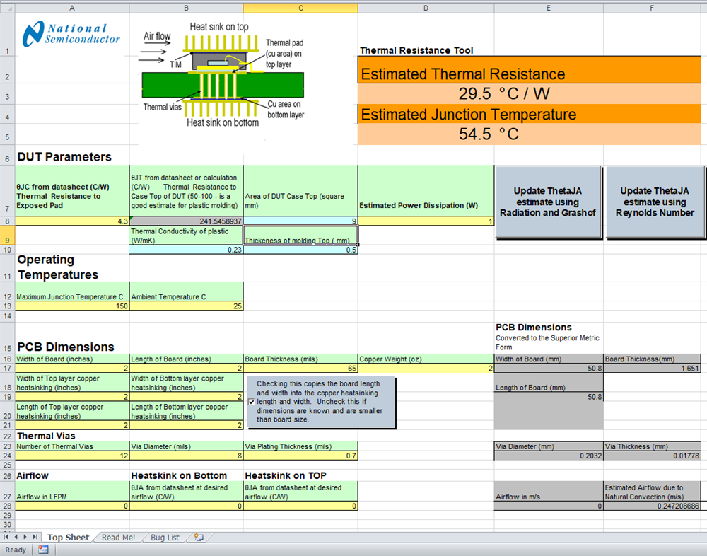
The basic heat flow equations can be solved using a spreadsheet and some simplifying assumptions. AN-2020 Thermal Design By Insight, Not Hindsight Application Report and the accompanying spread sheet provide a simple way to calculate thermal resistance for different PCB designs. A snap shot of the calculator output is shown in Figure 7-1.
 Figure 7-1 Screenshot of PCB Thermal Calculator.
 For a board of four square inches (about 26 cm2) the calculator gives a θJA of about 29°C/W. This compares favorably with the data in Figure 5-1 and the simple guideline estimate. This spreadsheet also takes into account the number and size of thermal vias used in the design. It can be used to quickly and easily examine the effects of different PCB designs on the thermal performance of the application. For more information see AN-2020 Thermal Design By Insight, Not Hindsight Application Report.