SNVA962 December 2020 TPSM5601R5H
2.1 Output Current Calculations
The peak current limit of the converter indicates the maximum peak inductor current which limits the output current (similar if implementing valley current limit). In the IBB configuration, the inductor current and peak switching currents are larger than in the equivalent buck converter. Consequently, the output current capability in the IBB topology is less than the buck configuration for the same current limit specifications. The maximum achievable current is calculated by Equation 1.

where
- IL_MAX is the maximum rated inductor current
- D is the operating duty cycle
Calculate the operating duty cycle for an inverting buck-boost converter using Equation 2.

where
- η = Efficiency
The efficiency term in Equation 2 adjusts the equations in this section for power conversion losses and yields a more accurate maximum output current result. Given that the IBB configuration yields different efficiency values compared to a buck, use a conservative value or see Table 2-1 or Figure 5-1 for typical efficiency values. Use Equation 2 to find the expected duty cycle, then use Equation 1 to calculate the recommended maximum output current. For example, in a 24-V input voltage, –5-V output voltage system, the duty cycle is:

The result of Equation 3 is then used to calculate the maximum recommended output current:

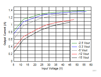
Table 2-1 and Figure 2-1 provide a general idea of the recommended maximum output current allowed from the TPSM5601R5H in an inverting configuration, with given typical efficiency values.
| VOUT (V) | VIN (V) | IL_MAX (A) | η | D | IOUT (A) |
|---|---|---|---|---|---|
| –2.5 | 24 | 1.5 | 0.69 | 0.131 | 1.303 |
| –3.3 | 24 | 1.5 | 0.73 | 0.159 | 1.262 |
| –5 | 24 | 1.5 | 0.78 | 0.211 | 1.184 |
| –12 | 24 | 1.5 | 0.83 | 0.376 | 0.936 |
| –15 | 24 | 1.5 | 0.84 | 0.427 | 0.860 |
 Figure 2-1 Recommended Maximum Output
Current