SNVAA10 January 2021 LMR36015S , TPS54350-EP , TPS54354-EP , TPS543820E , TPS54622-EP , TPS62110-EP , TPS62111-EP , TPS62112-EP , TPS629210E , TPSM5D1806E
2.1 Solution Size vs. Thermals
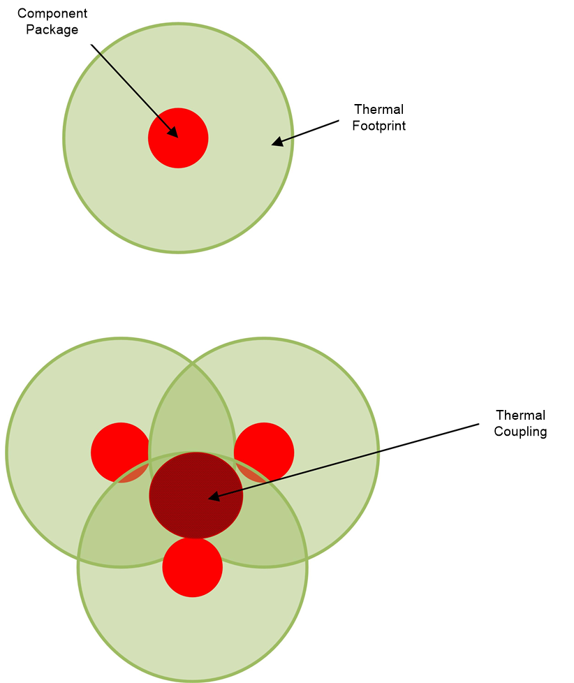
Thermal management becomes a main point of concern especially in high density systems. Keep in mind that not only is the heat dissipated by the converter affecting itself and nearby circuits, but it is also experiencing heat from nearby components. It turns out that placing heat producing components too close together can have a larger effect on thermal performance than one would think. This is where an extended temperature device can be very beneficial. Figure 2-1 illustrates an example of a heat generating component in a defined thermal footprint. A thermal footprint is the area of the PCB that is part of the radiation and convection of the package. Usually, the copper on the printed circuit board (PCB) is used to help dissipate the heat. But, not all applications are flexible when it comes to board space. That is why in such circumstances, devices with extended temperature capabilities will strive.
 Figure 2-1 Example of Thermal Footprint Concept