SNVU754A October   2021  – November 2021 LM5013-Q1


  1.   Trademarks
  2. 1General TI High Voltage Evaluation User Safety Guidelines
  3. 2Overview
    1. 2.1 LM5013-Q1 Asynchronous Buck Converter
  4. 3LM5013-Q1 Evaluation Module
    1. 3.1 Quick Start Procedure
    2. 3.2 Detailed Descriptions
  5. 4Schematic
  6. 5PCB Layout
  7. 6Bill of Materials
  8. 7Performance Curves
  9. 8Revision History

Performance Curves

For performance curves, in addition to those shown in Figure 7-1, please visit LM5013-Q1 data sheet's application section. Applications curves would be taken on LM5013-Q1 EVM unless otherwise specified.
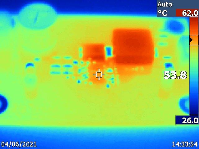
GUID-20210726-CA0I-V9HH-FNKN-G6JBWBSCDHNR-low.jpg Figure 7-1 Thermal Capture of EVM: VIN = 48-V, VOUT = 12-V, IOUT= 1.5-A
Note the design was optimized for small size and as a result, the thermal performance of the EVM does not reflect expected system performance with larger copper area. If continuous evaluation is to be done at higher input voltage, load current, or both, a fan must be used to make sure the IC does not hit its thermal limit.

Ensure the hot temperature identifiers are noticed on the PCB and care is taken in the handling of the PCB.