SPRACM9B June 2019 – November 2020 F29H850TU , F29H859TU-Q1 , TMS320F28384D , TMS320F28384S , TMS320F28386D , TMS320F28386S , TMS320F28388D , TMS320F28388S , TMS320F28P650DH , TMS320F28P650DK , TMS320F28P650SH , TMS320F28P650SK , TMS320F28P659DH-Q1 , TMS320F28P659DK-Q1 , TMS320F28P659SH-Q1
- Trademarks
- 1 Introduction
- 2 Benefits of the TMS320F2838x MCU for High-Bandwidth Current Loop
- 3 Current Loops in Servo Drives
- 4 Outline of the Fast Current Loop Library
- 5 Fast Current Loop Evaluation
- 6 Incremental Build Level 1
- 7 Incremental Build Level 2
- 8 Incremental Build Level 3
- 9 Incremental Build Level 4
- 10Incremental Build Level 5
- 11Incremental Build Level 6
- 12Incremental Build Level 7
- 13Incremental Build Level 8
- 14References
- 15Revision History
9 Incremental Build Level 4
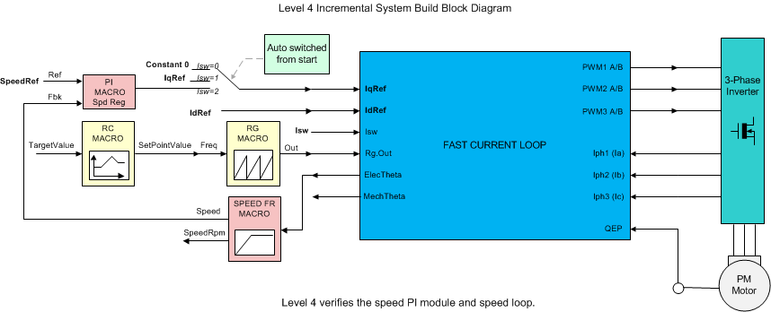
Assuming the previous section is completed successfully, this section verifies the speed PI module and speed loop. When the motor is commanded to run, it is subjected to an initial alignment stage where the electrical angle and the position encoder angle count are set to zero. After ensuring a stable alignment, the motor starts running.
- Open fcl_f2838x_tmdxiddk_settings_cpu1.h and select the level 4 incremental build option by setting the BUILDLEVEL to FCL_LEVEL4 (#define BUILDLEVEL FCL_LEVEL4).
- The current loop regulator can be selected to be PI controller or complex controller by setting FCL_CNTLR to PI_CNTLR or CMPLX_CNTLR.
- Select CURRENT_SENSE to LEM_CURRENT_SENSE
- Select POSITION_ENCODER to QEP_POS_ENCODER or T_FORMAT_ENCODER depending on the encoder coupled to motor.
- Select SAMPLING_METHOD to SINGLE_SAMPLING or DOUBLE_SAMPLING. If a T-format encoder is used, select SINGLE_SAMPLING and no more than 10KHz PWM frequency. For more information, see Section 5.1.3.3.
- Right-click on the project name, and then click Rebuild Project. When the build is complete, click the Debug button, reset the CPU, restart, enable real-time mode, and run.
In the software, the key variables to be adjusted are summarized as follows:
- speedRef: for changing the rotor speed in per-unit.
- IdRef: for changing the d-axis voltage in per-unit.
- IqRef: for changing the q-axis voltage in per-unit.
Figure 9-1 shows the implementation block diagram.
 Figure 9-1 Level 4 Block Diagram Showing Speed Loop With Inner FCL
The key steps are explained as follows:
- Set enableFlag to 1 in the watch window. The isrTicker variable is incrementally increased as seen in watch windows to confirm the interrupt is working properly.
- Set speedRef to 0.3 pu (or another suitable value if the base speed is different).
- Add pid_spd variable to the Expressions window
- Gradually increase voltage at variac to get an appropriate DC-bus voltage.
- Set runMotor to MOTOR_RUN
- Notice that the state machine variable (lsw) is auto-promoted in a sequence, its states are as follows:
- lsw = ENC_ALIGNMENT --> lock the rotor of motor into alignment with stator phase A
- lsw = ENC_WAIT_FOR_INDEX --> motor in run mode and waiting for the first instance of QEP index pulse (applicable with QEP encoder only)
- lsw = ENC_CALIBRATION_DONE --> motor in run mode - (signifies occurence of QEP index pulse and completion of calibration when QEP is used, or, completion of calibration when other encoders are used)
- Compare the speed (speed1.Speed) with speedRef in the watch windows with the continuous refresh feature to see whether or not it is nearly the same.
- To confirm this speed PID module, try different values of speedRef (positive or negative). The P, I, and D gains may be tweaked to get a satisfactory response.
- At a very low speed range, the performance of the speed response relies heavily on the accuracy of rotor position angle provided by position encoder.
- Bring the system to a safe stop by reducing the bus voltage, taking the controller out of real-time mode, and resetting. Now the motor stops.
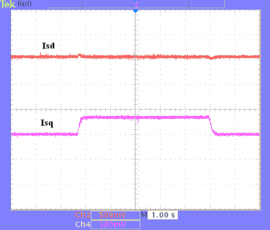
Figure 9-2 shows flux and torque components of the stator current in the synchronous reference frame.
 Figure 9-2 Flux and Torque Components of the Stator Current in the Synchronous Reference Frame Under 0.33-pu Step-Load and 0.3-pu Speed