SPRACO3 October 2019 INA240 , LMG5200 , TMS320F280021 , TMS320F280021-Q1 , TMS320F280023 , TMS320F280023-Q1 , TMS320F280023C , TMS320F280025 , TMS320F280025-Q1 , TMS320F280025C , TMS320F280025C-Q1 , TMS320F280040-Q1 , TMS320F280040C-Q1 , TMS320F280041 , TMS320F280041-Q1 , TMS320F280041C , TMS320F280041C-Q1 , TMS320F280045 , TMS320F280048-Q1 , TMS320F280048C-Q1 , TMS320F280049 , TMS320F280049-Q1 , TMS320F280049C , TMS320F280049C-Q1 , TMS320F28374D , TMS320F28374S , TMS320F28375D , TMS320F28375S , TMS320F28375S-Q1 , TMS320F28376D , TMS320F28376S , TMS320F28377D , TMS320F28377D-EP , TMS320F28377D-Q1 , TMS320F28377S , TMS320F28377S-Q1 , TMS320F28378D , TMS320F28378S , TMS320F28379D , TMS320F28379D-Q1 , TMS320F28379S
-
Dual-Axis Motor Control Using FCL and SFRA On a Single C2000 MCU
- Trademarks
- 1 Introduction
- 2 Benefits of the C2000 for High-Bandwidth Current Loop
- 3 Current Loops in Servo Drives
- 4 PWM Update Latency for Dual Motor
- 5 Outline of the Fast Current Loop Library
- 6 Evaluation Platform Setup
- 7 System Software Integration and Testing
- 8 Summary
- 9 References
5 Outline of the Fast Current Loop Library
The major challenge in digital motor control systems is the influence of the sample and hold (S/H) , as well as transportation delay inside the loop that slows down the system, impacting its performance at higher frequencies and running speeds. A minimal current loop time not only helps to improve the control bandwidth, but it also enables a higher modulation index (M-I) for the inverter. A higher M-I translates into the higher phase voltage that the inverter can apply on the motor. Higher loop latency will reduce the maximum available voltage and can restrict the rate of current change in the motor, thereby, adversely impacting the controller performance.
To overcome these challenges, a controller with high computational power, right set of control peripherals and superior control algorithm are needed. The TMS320F2837x and TMS20F28004x provide the necessary hardware support for higher performance, and the FCL algorithm from TI that runs on the C2000 MCU provides the needed algorithmic support.
To improve the operational range of FCL, the latency between feedback sampling and PWM update should be as small as possible. Typically, a latency of 2 µS or less is considered acceptable in many applications. Traditionally, this task is implemented using a combination of high end FPGAs, external ADCs and MCUs.
The FCL algorithm utilizes the following features in the F2837x or F28004x MCUs.
- Floating-Point Unit (FPU)
- Trigonometric and Math Unit (TMU)
- Three high speed 12-bit ADCs
- Multiple parallel processing blocks such as Control Law Architecture (CLA)
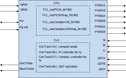
Figure 3 shows the block diagram of FCL algorithm with its inputs and outputs. The FCL partitions its algorithm across the CPU, CLA and TMU to bring down the latency to under 1.0 µs compared to the acceptable 2.0 µs. Further optimization is possible if the algorithm is written in assembly.
 Figure 3. Fast Current Loop Block Diagram
 The FCL algorithm supports two types of current regulators, a typical PI controller and a complex controller. The complex controller can provide additional bandwidth over the typical PI controller at higher speeds. Both current regulators are provided for user evaluation. In the example project, the current regulator can be selected by setting the FCL_CNTLR macro appropriately and studying how they compare.
Table 2 lists the FCL API functions and their descriptions.
Table 2. Summary of FCL Interface Functions
| API Function | Description |
|---|---|
| uint32_t FCL_getSwVersion(void ); | Returns a 32-bit constant and for this version the value returned is 0x00000008. |
| void FCL_initPWM(MOTOR_Vars_t *ptrMotor, uint32_t basePhaseU, uint32_t basePhaseV, uint32_t basePhaseW); | Initializes all motor control PWMs for FCL operation, this function is called by the user application during initialization process. Both motors call the same function, the difference is the passed parameters. |
| void FCL_initQEP(MOTOR_Vars_t *ptrMotor, const uint32_t baseA) | Assigned QEP base address of all motor control for FCL operation, this function is called by the user application during initialization process. Both motors call the same function, the difference is the passed parameters. |
| void FCL_resetController(MOTOR_Vars_t *ptrMotor) | Reset the FCL variables when user wants to stop the motor and restart the motor. |
| void FCL_runPICtrl_Mn(MOTOR_Vars_t *pMotor); | Function that performs the PI Control as part of the Fast Current Loop. (n=1 or 2 for motor 1 or motor 2) |
| void FCL_runPICtrlWrap_Mn(MOTOR_Vars_t *pMotor ); | Wrap up function to be called by the user application at the completion of FCL in PI Control Mode. (n=1 or 2 for motor 1 or motor 2) |
| void FCL_runComplexCtrl_Mn(MOTOR_Vars_t * pMotor ); | Function that performs the Complex control as part of the Fast Current Loop . (n=1 or 2 for motor 1 or motor 2) |
| void FCL_runComplexCtrlWrap_Mn(MOTOR_Vars_t *pMotor ); | Wrap up function to be called by the user application at the completion of FCL in Complex Control Mode . (n=1 or 2 for motor 1 or motor 2) |
For more information on the FCL algorithm, the source codes is available at : \ti\c2000\C2000Ware_MotorControl_SDK_version\libraries\fcl\source.
The algorithm is written in a modular format and is able to port over to user platforms using F2837x, F28004x, or F2838x devices if the following conditions are met:
- Motor phase current feedback are read into variables internal to the FCL functions. However, D-axis and Q-axis current feedback are available.
- PWM modules controlling motor phase A, B, and C are linked to the FCL.
- A QEP module connecting to the QEP encoder is linked to the FCL algorithm.
- CLA tasks one through eight are used by the FCL algorithm. This must be accommodated in the user application.