SPRACO3 October 2019 INA240 , LMG5200 , TMS320F280021 , TMS320F280021-Q1 , TMS320F280023 , TMS320F280023-Q1 , TMS320F280023C , TMS320F280025 , TMS320F280025-Q1 , TMS320F280025C , TMS320F280025C-Q1 , TMS320F280040-Q1 , TMS320F280040C-Q1 , TMS320F280041 , TMS320F280041-Q1 , TMS320F280041C , TMS320F280041C-Q1 , TMS320F280045 , TMS320F280048-Q1 , TMS320F280048C-Q1 , TMS320F280049 , TMS320F280049-Q1 , TMS320F280049C , TMS320F280049C-Q1 , TMS320F28374D , TMS320F28374S , TMS320F28375D , TMS320F28375S , TMS320F28375S-Q1 , TMS320F28376D , TMS320F28376S , TMS320F28377D , TMS320F28377D-EP , TMS320F28377D-Q1 , TMS320F28377S , TMS320F28377S-Q1 , TMS320F28378D , TMS320F28378S , TMS320F28379D , TMS320F28379D-Q1 , TMS320F28379S
-
Dual-Axis Motor Control Using FCL and SFRA On a Single C2000 MCU
- Trademarks
- 1 Introduction
- 2 Benefits of the C2000 for High-Bandwidth Current Loop
- 3 Current Loops in Servo Drives
- 4 PWM Update Latency for Dual Motor
- 5 Outline of the Fast Current Loop Library
- 6 Evaluation Platform Setup
- 7 System Software Integration and Testing
- 8 Summary
- 9 References
7.1.1 SVGEN Test
The 'speedRef' value is fed into the ramp control module to ramp up the speed command. The output of the ramp module is fed into a ramp generator to generate the angle for sine wave generation. This angle as well as the variables VdTesting and VqTesting feeds into inverse park transformation block which then feeds into space vector modulation modules to generate three phase PWMs.
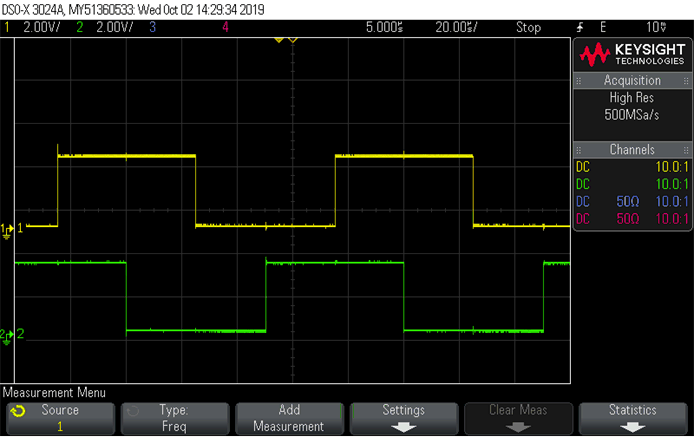
The PWM outputs from C2000 controller can be probed on scope a shown in Figure 19. There is a 90° shift between the PWM output of motor 1 and motor 2.
 Figure 19. PWM_UH of Motor 1 and Motor 2 on Scope Plots
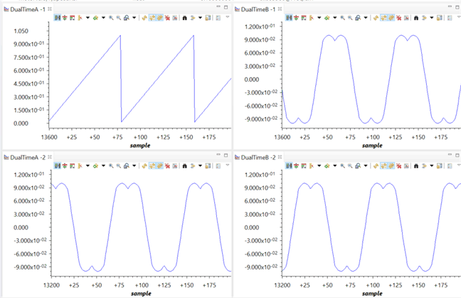
 The outputs from space vector generation module can be viewed using the graph tool from the debug environment as "Setup Graphs" operation step in Section 6.2.2.
Figure 20 shows the voltage vector angle, and the pulse width values for the phases A, B, and C and are denoted as Ta, Tb, and Tc, where Ta, Tb, and Tc waveform are 120° apart from each other. Specifically, Tb lags Ta by 120° and Tc leads Ta by 120°.These are generated based on the values of 'motorVars[0].speedRef','VdTesting' and 'VqTesting'. These values can be changed to see the impact on these waveform. Check the PWM test points on the board to observe PWM pulses and ensure that the PWM module is running properly.
 Figure 20. Voltage Vector Angle and SVGEN Ta, Tb, and Tc Using Graph Tool
 NOTE
The operation suggested above for motor 1 by setting 'motorVars[0]' that can be repeated for motor 2 by setting 'motorVars[1]' also to verify the related modules. To use the graph tool for motor 2, change the datalog pointer to the space vector generator module of motor 2 as the following example code in motor1ControlISR() in " dual_axis_servo_drive.c".
// -----------------------------------------------------------------------------
// Connect inputs of the DATALOG module
// -----------------------------------------------------------------------------
    dlogCh1 = motorVars[1].ptrFCL->rg.Out;
    dlogCh2 = motorVars[1].svgen.Ta;
    dlogCh3 = motorVars[1].svgen.Tb;
    dlogCh4 = motorVars[1].svgen.Tc;