SPRACY5 July   2021 AM67 , AM67 , AM67A , AM67A , AM68 , AM68 , AM68A , AM68A , AM69 , AM69 , AM69A , AM69A , DRA821U , DRA821U , DRA821U-Q1 , DRA821U-Q1 , DRA829J , DRA829J , DRA829J-Q1 , DRA829J-Q1 , DRA829V , DRA829V , DRA829V-Q1 , DRA829V-Q1 , TDA4AEN-Q1 , TDA4AEN-Q1 , TDA4AH-Q1 , TDA4AH-Q1 , TDA4AL-Q1 , TDA4AL-Q1 , TDA4AP-Q1 , TDA4AP-Q1 , TDA4VE-Q1 , TDA4VE-Q1 , TDA4VEN-Q1 , TDA4VEN-Q1 , TDA4VH-Q1 , TDA4VH-Q1 , TDA4VL-Q1 , TDA4VL-Q1 , TDA4VM , TDA4VM , TDA4VM-Q1 , TDA4VM-Q1 , TDA4VP-Q1 , TDA4VP-Q1


  1.   Trademarks
  2. 1Introduction to Flashing Tools
    1. 1.1 Trace32/Lauterbach
    2. 1.2 CCS-Based Flash Writer
    3. 1.3 Other Software Tools
  3. 2Flash Devices on TDA4
    1. 2.1 Flashing OSPI and eMMC RAW Sectors
    2. 2.2 Flashing eMMC User Partition
  4. 3Prerequisites for Flashing TDA4
    1. 3.1 Boot Switch Settings
    2. 3.2 How to Generate a Tiny File System
    3. 3.3 Generating the eMMC tisdk-tiny-image.img
    4. 3.4 Running Until u-boot
      1. 3.4.1 UART Boot Mode
      2. 3.4.2 DFU Boot
      3. 3.4.3 SD Boot or any Other Boot Mode
    5. 3.5 Configuring Boot0 Partition and Partitioning eMMC
  5. 4OSPI Flashing
    1. 4.1 Flashing Bootloader Binaries
      1. 4.1.1 TI UNIFLASH Tool
        1. 4.1.1.1 Flashing Instructions
        2. 4.1.1.2 Linux Boot Binaries
        3. 4.1.1.3 RTOS Boot Binaries
    2. 4.2 dfu-util
      1. 4.2.1 Flashing Instructions
    3. 4.3 CCS/JTAG
      1. 4.3.1 Flashing Instructions
    4. 4.4 Trace32/Lauterbach
      1. 4.4.1 Flashing Instructions
    5. 4.5 u-boot
      1. 4.5.1 Flashing Instructions
  6. 5eMMC flashing
    1. 5.1 Flashing Bootloader Binaries
      1. 5.1.1 TI UNIFLASH Tool
        1. 5.1.1.1 Flashing Instructions
      2. 5.1.2 Trace32/Lauterbach
        1. 5.1.2.1 Flashing Instructions
      3. 5.1.3 dfu-util
        1. 5.1.3.1 Flashing Instructions
    2. 5.2 u-boot
      1. 5.2.1 Flashing Instructions
    3. 5.3 eMMC UDA Partition Flashing With tinyrootfs
      1. 5.3.1 dfu-util
      2. 5.3.2 u-boot + CCS/JTAG
        1. 5.3.2.1 Flashing Instructions

Flash Devices on TDA4

OSPI and eMMC flashes on popular choice of external flashes used on TDA4 boards. Figure 2-1 depicts the default layout for the flash in the SDK, which can be changed in case the custom applications need a different layout.
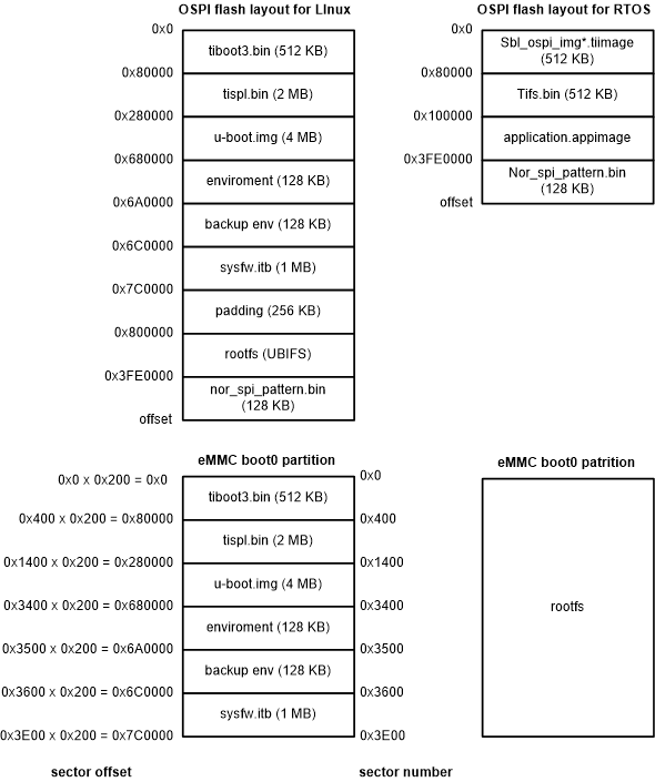
GUID-20210624-CA0I-FPH5-26DX-RKVBS6FNPSNZ-low.gif Figure 2-1 Flash Layout in SDK