SPRADE8A November 2023 – April 2024 F29H850TU , F29H859TU-Q1 , TMS320F28P650DH , TMS320F28P650DK , TMS320F28P650SH , TMS320F28P650SK , TMS320F28P659DH-Q1 , TMS320F28P659DK-Q1 , TMS320F28P659SH-Q1
- 1
- Abstract
- Trademarks
- 1 Introduction
- 2 Difference Between EEPROM and On-Chip Flash
- 3 Overview
- 4 Software Description
-
5 Ping-Pong Emulation
- 5.1 User-Configuration
- 5.2
EEPROM Functions
- 5.2.1 EEPROM_Config_Check
- 5.2.2 Configure_Protection_Masks
- 5.2.3 EEPROM_Write
- 5.2.4 EEPROM_Read
- 5.2.5 EEPROM_Erase
- 5.2.6 EEPROM_GetValidBank
- 5.2.7 EEPROM_UpdateBankStatus
- 5.2.8 EEPROM_UpdatePageStatus
- 5.2.9 EEPROM_UpdatePageData
- 5.2.10 EEPROM_Get_64_Bit_Data_Address
- 5.2.11 EEPROM_Program_64_Bits
- 5.2.12 EEPROM_CheckStatus
- 5.2.13 ClearFSMStatus
- 5.3 Testing Example
-
6 Single-Unit Emulation
- 6.1 User-Configuration
- 6.2
EEPROM Functions
- 6.2.1 EEPROM_Config_Check
- 6.2.2 Configure_Protection_Masks
- 6.2.3 EEPROM_Write
- 6.2.4 EEPROM_Read
- 6.2.5 EEPROM_Erase
- 6.2.6 EEPROM_GetValidBank
- 6.2.7 EEPROM_Get_64_Bit_Data_Address
- 6.2.8 EEPROM_UpdateBankStatus
- 6.2.9 EEPROM_UpdatePageStatus
- 6.2.10 EEPROM_UpdatePageData
- 6.2.11 EEPROM_Get_64_Bit_Data_Address
- 6.2.12 EEPROM_Program_64_Bits
- 6.2.13 EEPROM_CheckStatus
- 6.2.14 ClearFSMStatus
- 6.3 Testing Example
- 7 Application Integration
- 8 Adapting to Other Gen 3 C2000 MCUs
- 9 Flash API
- 10Source File Listing
- 11Troubleshooting
- 12Conclusion
- 13References
- 14Revision History
5.3 Testing Example
The examples provided were tested with F28P650DK9. To properly test the example, the memory window and breakpoints need to be utilized within Code Composer Studio. The following steps were followed to program and test the project.
- Connect the F28P650DK9 to the PC via USB and an XDS110 Debug Probe with JTAG connection.
- Connect a 5V DC power supply to the board.
- Start Code Composer Studio and open the F28P65x_EEPROM_PingPong_Example.pjt.
- Build the project by selecting Project -> Build Project.
- Launch the Target Configurations by going to View -> Target Configurations -> F28P65x_EEPROM_PingPong_Example -> targetConfigs -> right-click TMS320F28P650DK9.ccxml -> Launch Selected Configuration.
- Connect to CPU1 by going to the Debug window, right clicking Texas Instruments XDS110 USB Debug Probe_0/C28xx_CPU1, and selecting Connect Target.
- Load symbols by clicking Load Symbols and selecting the F28P65x_EEPROM_PingPong.out from the project.
- Set breakpoints to properly view data written to and read from the memory within the memory window as shown in Break Points.
 Figure 5-2 Break Points
 - Run to the first break-point and open the Memory Browser (View -> Memory Browser) to view the data. Bank_Pointer can be used to watch the data written and Read_Buffer to watch the data being read back from the memory. This is shown in Write to EEPROM Unit and Read Data.
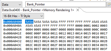 Figure 5-3 Write to EEPROM Unit
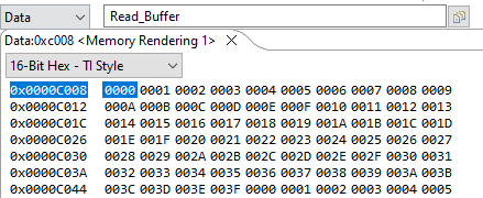 Figure 5-4 Read Data
 - Continue running from break-point to break-point until the program has finished or EEPROM is full.
- Once EEPROM is full, you will see the new data written to the previously inactive unit and the full EEEPROM will be erased. Shown in Write to new EEPROM Unit and Erase full EEPROM Unit.
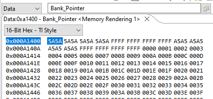 Figure 5-5 Write to new EEPROM Unit
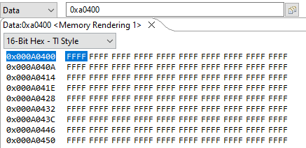 Figure 5-6 Erase full EEPROM Unit
 - This process can be repeated between the two EEPROM units as necessary.
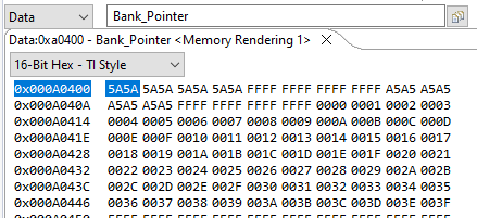 Figure 5-7 Write to original EEPROM unit
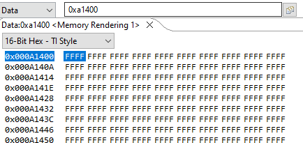 Figure 5-8 Erase full EEPROM Unit
The preceding steps were used to test the Page Mode configuration. The 64-Bit Mode configuration can also be tested with the same procedure. To enable 64-Bit Mode, change the definition in the EEPROM_PingPong_Config.h file by un-commenting the _64_BIT_MODE directive and commenting out the PAGE_MODE directive.