SPRADP0 December 2024 AM2631 , AM2631-Q1 , AM2632 , AM2632-Q1 , AM2634 , AM2634-Q1 , AM263P4 , AM263P4-Q1
3.3 Lauterbach® Connections
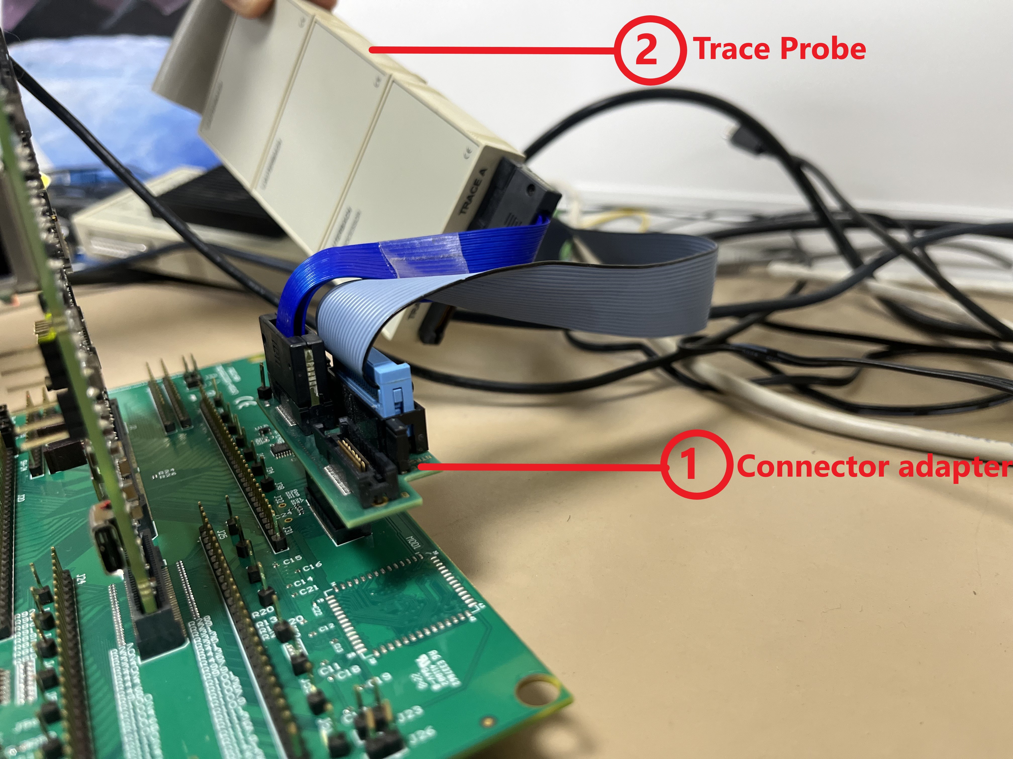
- Connect the Lauterbach adapter to the Dock board.
- Connect the Lauterbach trace probe to the same port (A or B) as on the adapter connected to the Dock board.
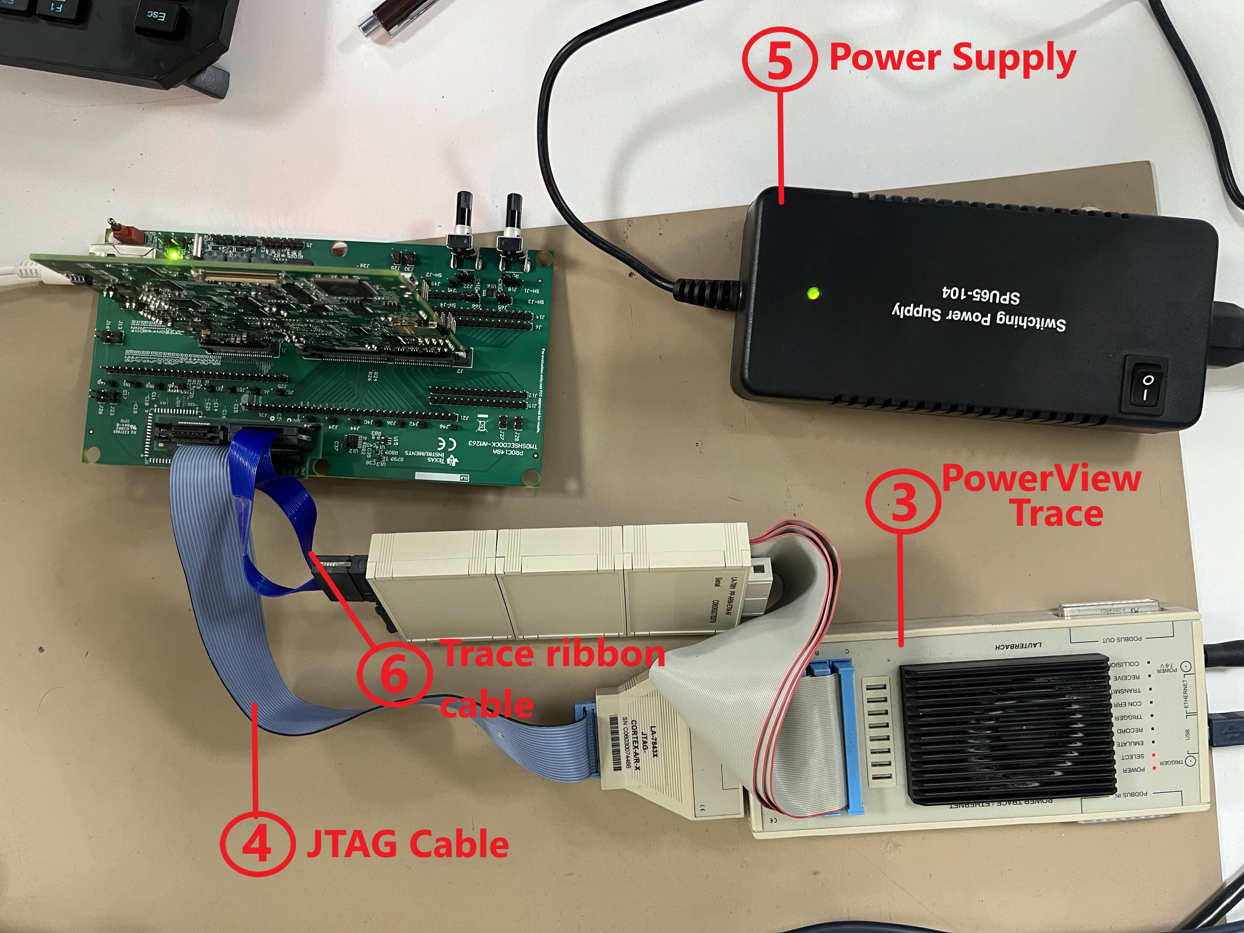
- Make sure the Trace probe and PowerView trace are connected properly to the adapter.
- Connect the JTAG cable between PowerView Trace and adapter.
- Connect the Lauterbach power supply to the PowerView trace and power on the hardware.
- Connect the Trace ribbon cable between the Trace probe and adapter.
 Figure 3-5 Lauterbach Setup
Connections
 Figure 3-6 Lauterbach Setup Connections
 Now, users can power on the Lauterbach power supply.