SPRADP0 December 2024 AM2631 , AM2631-Q1 , AM2632 , AM2632-Q1 , AM2634 , AM2634-Q1 , AM263P4 , AM263P4-Q1
3.2 AM263Px Connections
The AM263Px schematics differ from the AM263x. As a result, some of the steps can be different in-case of AM263Px.
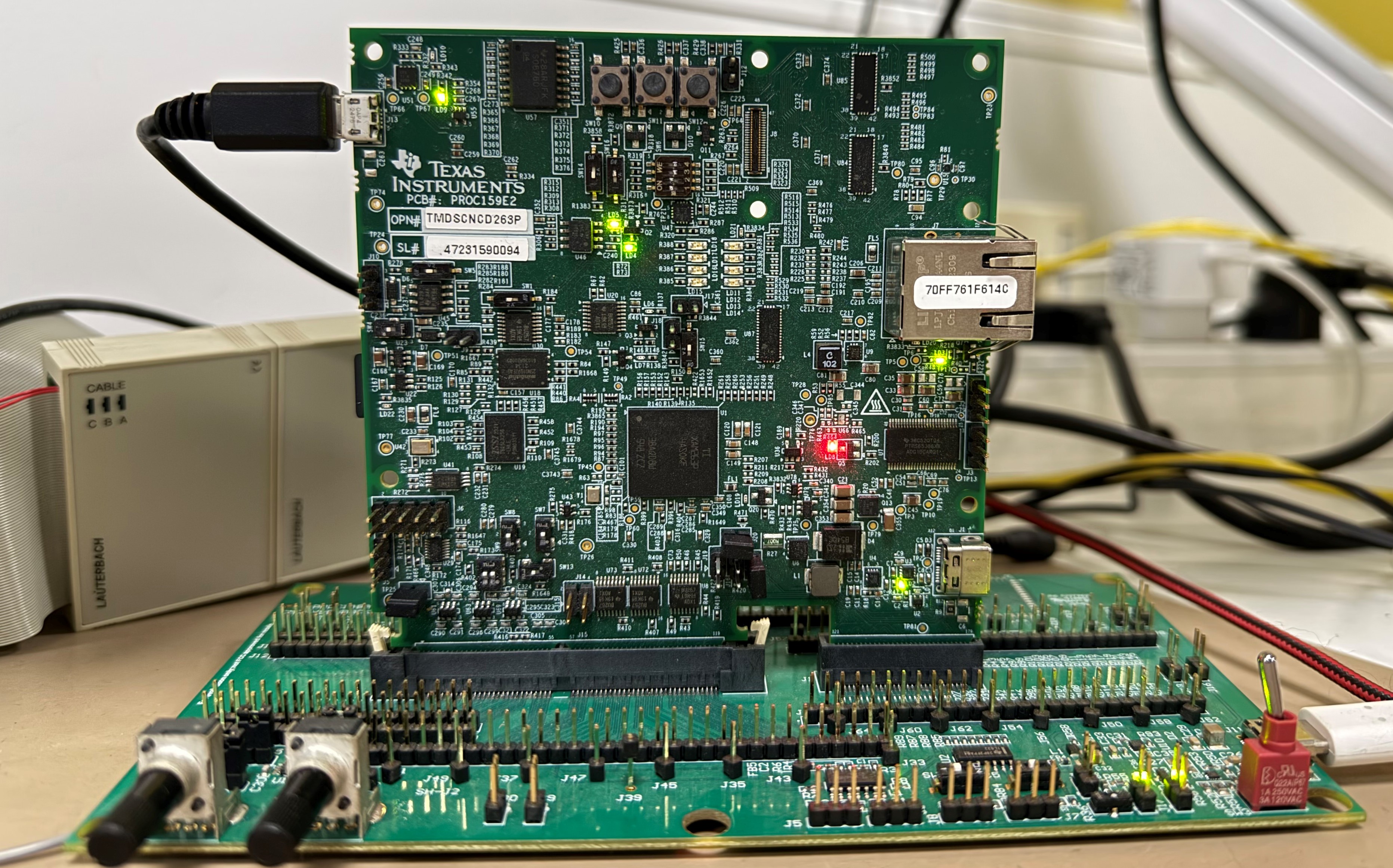
- Dock the AM263Px device on the HSEC Dock breakout board.
- Connect the power supply to the HSEC Dock breakout board.
- Connect the USB Type-A to micro-B from the Host PC to the AM26x microcontroller.
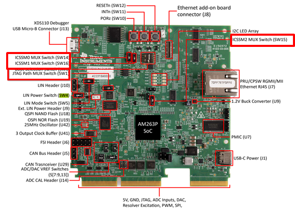
- On the AM263Px, put the SW-1 switch to OFF to
disconnect the onboard debugger. Next, put SW-14 switch to OFF, SW-15 switch to
OFF and SW-16 switch to ON state. This is necessary to route the signals to the
HSEC board to which the Lauterbach trace pins are connected.
Switch
State
SW-1
Low
SW-14
Low SW-15
Low SW-16
High
- Power on the HSEC Dock breakout board. LD2, LD4, LD5, LD9 glows on the AM263Px.
 Figure 3-3 AM263Px PCB# PROC E2
Switches
 Figure 3-4 AM263Px Control Card Mounted
on HSEC Dock Board