SPRUJB1 December 2023 AM68 , AM68A , AM69 , AM69A , TDA4AH-Q1 , TDA4AP-Q1 , TDA4VH-Q1 , TDA4VP-Q1
3.1 Use Case
The use case page is shown in Figure 3-1. This sheet has 10 different sections that must be completed.
Core Processor Utilization:
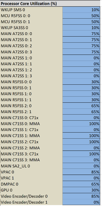
This block allows the user to assign a utilization to each major core IP.
WKUP domain:
- SMS 0 – Arm Cortex-M4F based Security Management Subsystem
- SA3SS 0 – a collection of essential hardware accelerators supporting cryptography
MCU domain:
- Dual-R5F MCU Subsystem
Main domain:
- 2x Quad-A72 MPU Subsystem
- 3x Dual-R5F MCU Subsystems
- 4x C71x DSP Subsystem that includes a Matrix Multiplication Accelerator (MMA)
- SA2_UL is a collection of hardware accelerators supporting cryptography
- 2x Vision Preprocessing Accelerator (VPAC)
- Depth and Motion Processing Accelerator (DMPAC)
- Graphics Processing Unit (GPU)
- 2x Combination Video Encoder and Decoder
Key IP Frequency selection:
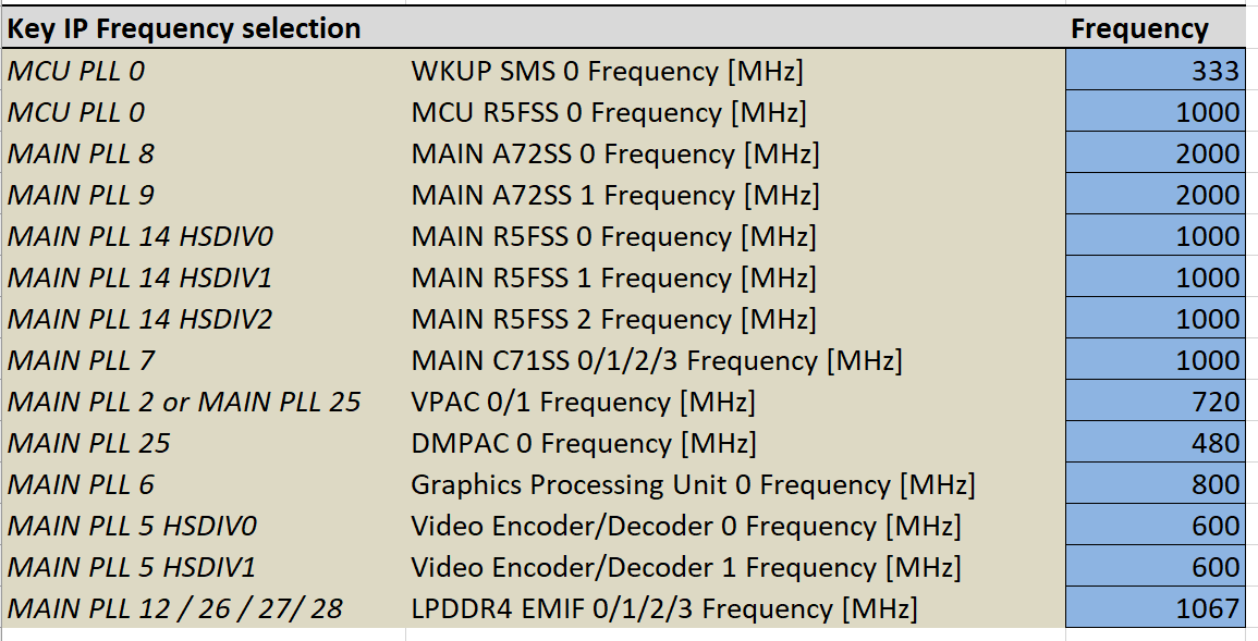
This block allows the user to select the frequency for the key blocks in the core utilization block (+DDR).
- One special note involves PLL25. Since the internal frequency of the PLL is limited to ~3GHz, the VPAC and DMPAC cannot simultaneously run at the highest frequency (720MHz and 520MHz, respectively) for both IPs from the same PLL.
Memory Interfaces:
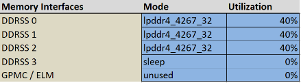
The AM69x device has 4 Double Data Rate (DDR) SDRAM controllers and associated physical layer interfaces (PHYs) as well as a General-Purpose Memory Controller (GPMC) with Error Location Module (ELM).
PHYs:
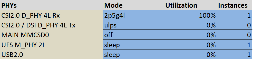
The AM69x device has several PHYs; for the PHYs with multiple instances, in addition to the mode and the utilization, the user should also select how many of the instances are used:
- 3x Camera Stream Interface (CSI) 2.0 Receive PHYs each with 4 Lanes
- 2x CSI2.0 Transmit PHYs each
with 4 Lanes
- 2x Display Subsystem Display Serial Interface (DSI) Transmit interface (using the CSI2.0 Tx PHY)
- 1x Multi Media Card Interface (MMC) for eMMC only
- 1x Universal Flash Storage PHY with 2 lanes
- 1x Universal Serial Bus (USB) 2.0 PHY
High Speed Serial Interface:
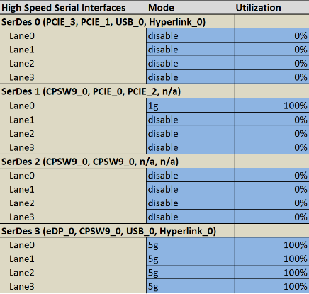
There are four high speed serializing / deserializing (SerDes) interface on this device. Each SerDes has 4 lanes for which the mode, utilization and IP should be selected.
- The IP loading (utilization) is required to be configured in the IP Utilization for High Speed IO
- Because the SerDes constantly transmit (e.g. SGMII sends /I1/ and /I2/ ordered sets when not sending data), the utilization should likely be set to 100%.
IP Utilization for High Speed IO
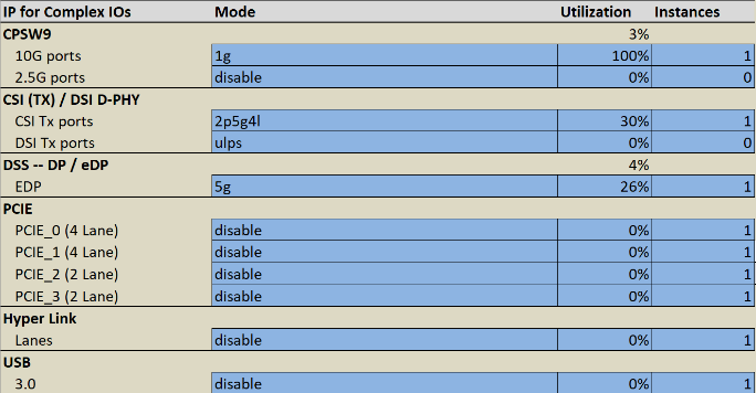
The tool cannot determine the loading of the IP from the SerDes loading. Therefore, it is required that the user enter the IP loading in this table as well as entering the SerDes loading.
Environmental:
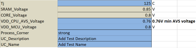
The environmental section allows the user to define junction temperature (Tj), VDD_CPU_AVS voltage, VDD_MCU voltage, the process corner, and a use case name and description.
- The PDN / Peak estimate will be run with Strong silicon and at either 105°C or 125°C; see Footnote 1.
- To save the use case, the user must supply a name for the use case.
LVCMOS IOs
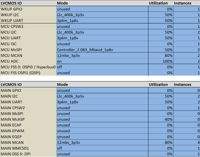
Like the PHY section, the user enters Mode, utilization, and instances for each LVCMOS.
There is only one mode and utilization allowed per IP (customization is not supported since the corresponding IP blocks do not contribute significantly to the overall power). If a system uses multiple modes for an IP type, the highest power mode should be used.
Buttons:
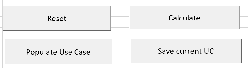
The buttons initialize different phases of the power estimation.
- Reset clears and resets the form as well as clearing Results
- Populate Use Case – It is recommended to start any power estimate by using one of the pre-configured representative use cases. This helps to highlight how the tool can be used in a reasonable way (i.e., it is usually not appropriate to enter 100% for all of the IP on the SoC).
- Calculate – once the form is completed, calculate in order to populate data into Results
- Save current UC – once the user gets a test case competed, it can be saved if a UC Name has been supplied. Once a use case is saved it will be part of the “Starting Use Case” list and be re-populated with the Populate use case button.
When each button is pushed, the cells underneath the button (H8:I11) record that it was started and then record when the step completes.
Starting Use Case:
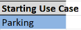
This drop down selects the use case to pre-populate.
This set of use cases is supplemented when the user saves the current UC (with the buttons described above).
The pre-populated use cases are intended to provide TI-generated starting points for the customer’s use case. In the final section of this user guide, some of the pre-populated use cases will be discussed.