The Value of a Thin, Isolated Power Solution
Orlando Murray
Faced with shrinking space constraints and increased robustness requirements, industrial and automotive power-supply designers must carefully choose the best power design topologies to meet their application needs. Isolated choices include modules as well as discrete and integrated solutions; each has its own trade-offs. Modules are encapsulated solutions with common input/output requirements, but they have limited temperature and isolation ratings. Discrete solutions are customized designs using individual components, but they require a large engineering effort. Integrated solutions use transformers inside the package for a lower profile solution, but they have lower power outputs.
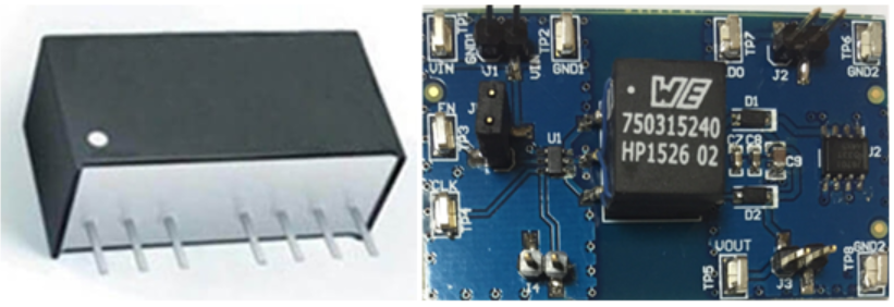
Modules and discrete solutions use transformers or inductors to convert electric energy. The transformer is a tall component, which causes modules and discrete solutions to have significant height. Figure 1 shows a 3D view of a module and a top-down view of a discrete solution.
 Figure 1 Isolated power solutions:
module on the left, discrete on the right
Figure 1 Isolated power solutions:
module on the left, discrete on the rightApplications requiring low board thickness are limited by the height of the solution. For example, telecommunication racks use slotted cards to add or replace servers. The thinner these cards are, the more server slots can fit in each rack. Industries like telecommunications and consumer electronics pushing for low-profile designs can benefit from a thin, integrated power solution.
Thin solutions have a mechanical advantage as well. Compared to other printed circuit board (PCB) components, transformers are tall – like a high-rise in the middle of a residential community. These tall components act like cantilevers and are susceptible to strong physical perturbations on the PCB, just like a high-rise in an earthquake. Cantilever vibration modes lead to lateral stresses at the top of the component, as illustrated in Figure 2.
 Figure 2 Discrete solution with
transformer flexibility illustrated in white
Figure 2 Discrete solution with
transformer flexibility illustrated in whiteLateral stress can cause transformer pads to lift or components to desolder from the PCB. This can be a huge reliability issue in rugged application environments that will experience impacts and vibrations. For example, isolated drivers powering AC motors can experience vibrations related to motor speeds during operation. If the vibrations get too violent, a motor can cause its own failure by disconnecting the transformer from its power-stage gate driver.
Even with minimal vibrations, one unexpected impact can potentially disable motor drives. Imagine in factory automation that an impact causes a motor failure, slowing down or stopping production. Or for an electric vehicle, hitting a speed bump too fast could potentially disable the electric motor. Thin, low-profile designs are critical for circuit lifetime reliability in environments with vibrations and impacts, such as automotive electric motors and industrial automation.
TI's UCC12051-Q1 is an integrated isolated DC/DC converter that leverages transformer-in-package technology, providing 500 mW of isolated power in a low-profile 16 pin small-outline integrated circuit (SOIC16-DW) package. The device is operable in extended ambient temperatures from -40°C to 125°C and features 5-kV reinforced isolation.
Thin board designs allow for smaller, denser systems, and are more mechanically robust to vibrations and perturbations. The UCC12051-Q1 enables low-profile power for thinner board designs compared to modules and integrated solutions. Medical and consumer industries can benefit from lower profiles systems, and telecommunication and industrial industries can benefit from increased reliability and power density.
IMPORTANT NOTICE AND DISCLAIMER
TI PROVIDES TECHNICAL AND RELIABILITY DATA (INCLUDING DATASHEETS), DESIGN RESOURCES (INCLUDING REFERENCE DESIGNS), APPLICATION OR OTHER DESIGN ADVICE, WEB TOOLS, SAFETY INFORMATION, AND OTHER RESOURCES “AS IS” AND WITH ALL FAULTS, AND DISCLAIMS ALL WARRANTIES, EXPRESS AND IMPLIED, INCLUDING WITHOUT LIMITATION ANY IMPLIED WARRANTIES OF MERCHANTABILITY, FITNESS FOR A PARTICULAR PURPOSE OR NON-INFRINGEMENT OF THIRD PARTY INTELLECTUAL PROPERTY RIGHTS.
These resources are intended for skilled developers designing with TI products. You are solely responsible for (1) selecting the appropriate TI products for your application, (2) designing, validating and testing your application, and (3) ensuring your application meets applicable standards, and any other safety, security, or other requirements. These resources are subject to change without notice. TI grants you permission to use these resources only for development of an application that uses the TI products described in the resource. Other reproduction and display of these resources is prohibited. No license is granted to any other TI intellectual property right or to any third party intellectual property right. TI disclaims responsibility for, and you will fully indemnify TI and its representatives against, any claims, damages, costs, losses, and liabilities arising out of your use of these resources.
TI’s products are provided subject to TI’s Terms of Sale (www.ti.com/legal/termsofsale.html) or other applicable terms available either on ti.com or provided in conjunction with such TI products. TI’s provision of these resources does not expand or otherwise alter TI’s applicable warranties or warranty disclaimers for TI products.
Mailing Address: Texas Instruments, Post Office Box 655303, Dallas, Texas 75265
Copyright © 2023, Texas Instruments Incorporated