SSZT238 october 2020 ISOS141-SEP
With the growing popularity of digital isolators in industrial and automotive applications, it can be overwhelming to select the best device for your system from the plethora of available options. Adding to this challenge, most digital isolators are designed with specific system requirements and applications in mind, leaving you to sort through endless specifications and features to ensure that the device you have selected will meet your system’s requirements.
Finding the “right” device doesn’t have to be complicated, however. In this article, I’ll walk through some of the primary decisions for selecting a digital isolator that I hope will help simplify your search.
Step one: understanding your isolation specification requirements
The first step is to understand your system’s isolation specification requirements. While requirements can sometimes feel like an open-ended list, to get started, consider these requirements related to common isolation design:
- Isolation withstand voltage (VISO). Is basic isolation and ≤3,000 VRMS sufficient for your design, or do you require ≥5,000 VRMS? Regulatory requirements often dictate this specification, which represents the voltage the isolator can handle without breakdown for at least 60 s.
- Working voltage (VIOWM). What is the consistent voltage that your isolation barrier needs to withstand for the lifetime of the product? Factors such as package size, pollution degree and material group can affect the working voltage of a component.
- Surge isolation rating (VIOSM). Does the design require reinforced isolation? If so, you will need an isolator that can withstand >10-kV surge pulses.
- Creepage/clearance. Is 4-mm creepage/clearance sufficient, or does your system standard require 8 mm or even higher? This specification will be dictated by the isolators package and lead frame.
- Common-mode transient immunity (CMTI). Will the system be in a noisy environment such as motor drives or solar inverters, where data integrity is critical and any bit errors can result in dangerous short-circuit events? If so, a high CMTI rating will be critical for your digital isolator.
- Power consumption. Is overall system power consumption a critical specification for your application; for example, is the system 4- to 20-mA loop-powered or battery-powered? If so, consider the per-channel current consumption specifications of each device.
- Data rate. What data rate does your communication interface require? Are you running slow universal asynchronous receiver transmitter speeds or high-speed ≥100-Mbps data protocols? In that case, you may consider each devices' maximum data rate.
Step two: selecting the right package
Once you have narrowed down your digital isolator specification requirements, the next step is to consider different package options. Packages can make a big difference when it comes to isolation, since the size and characteristics of the package directly affect a device’s high-voltage capabilities. Some of the same requirements in the list above (creepage, clearance, VIOWM, VIOSM, VISO) also influence package selection. A larger package with wider creepage and clearance will allow for higher isolation voltage specifications. If you can meet your system’s regulatory requirements with a smaller package option, a smaller package will of course help save both board space and cost. Additionally, you will want to consider how many channels of isolation your communication interface requires since higher channel counts dictate package type.
Step three: determining channel count and configuration
After specifications and requirements and packaging, there are just a few more options to consider. Determining how many channels of isolation you need for your signals and which direction each signal will go will help you determine your channel count and channel configuration. And considering your preferred default output state (or fail-safe state) will help you determine the predefined state of the output pin (either high or low) when the input channel of a digital isolator is unpowered or the pins are left floating. Options may be available for both default-high and default-low outputs.
Step four: assessing available devices
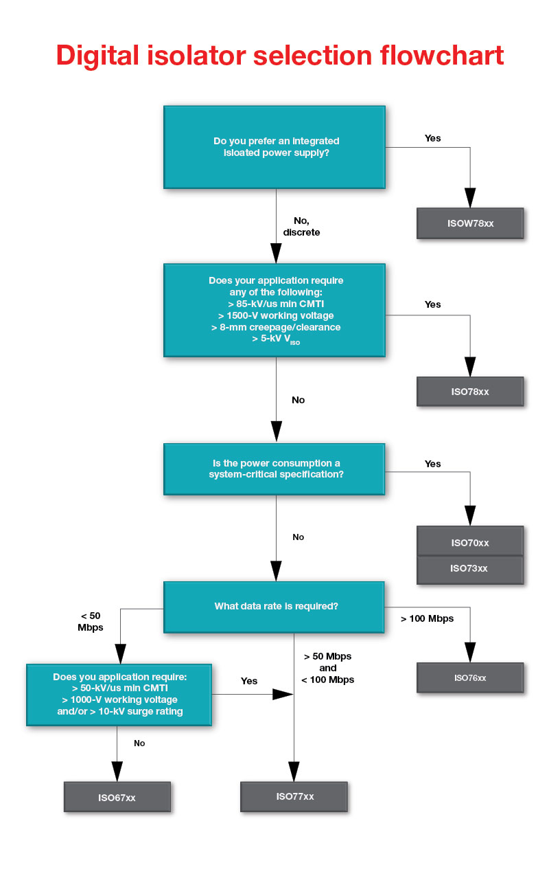
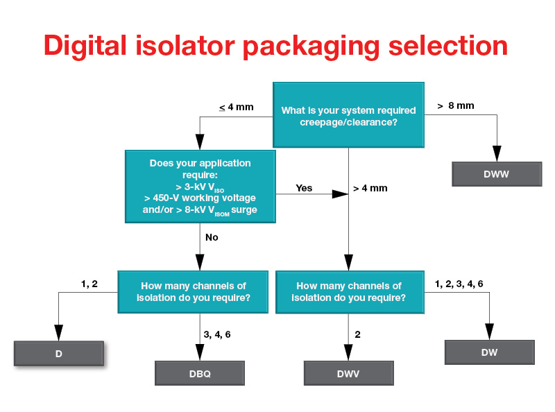
If you’re ready to put your digital isolator knowledge into practice, Figure 1 is a simple digital isolator selection flowchart that can help you determine the right device for your design. Figure 2 can help guide you to the right package designator and Figure 3 shows each package to scale, side by side.
 Figure 1 TI Digital Isolator Selection Flowchart
Use this list to learn more about the devices in the TI digital isolator selection flowchart:
- ISO67xx: Basic and reinforced isolation for cost-sensitive applications.
- ISO77xx: Basic and reinforced digital isolators.
- ISO78xx: Highest isolation rating, widest creepage/clearance, reinforced digital isolators.
- ISO70xx: Ultra-low power digital isolators.
- ISO73xx: Low-power, low-jitter digital isolators.
- ISO76xx: High-speed, 150-Mbps isolation.
- ISOS141-SEP: Radiation-tolerant digital isolator
 Figure 2 TI Digital Isolator Package Type Selection Flowchart
 Figure 3 Comparison of Available Package Options
Conclusion
There are many options when it comes to digital isolator products. Understanding your system and design requirements and leveraging the resources in this article will help you select the best digital isolator for your design. Selecting the “right” device could optimize your system’s overall design - helping you more easily meet regulatory requirements and your ability to develop reliable applications while staying within budget.
Additional resources
- Learn more about TI’s industry-leading isolation technology by reading the white paper, “Enabling high voltage signal isolation quality and reliability.”
- Get a better understanding for important high-voltage isolation parameters in the white paper, “High-voltage reinforced isolation: definitions and test methodologies.”
- View all of TI’s digital isolator certifications.