SSZTBV8 november 2015 ISO5851 , ISO5852S
AC motor-drive systems, also known as adjustable-speed power drives or variable-frequency drives, are smart motor-control systems. These systems use sophisticated power electronics that control the speed, torque and position of a motor, rather than running the motor at a fixed speed and using mechanical elements to control these parameters. Used widely in industrial applications, AC motor drives vastly improve the efficiency and control of motor-drive systems.
In an earlier blog post, I discussed the use of isolators for protection against high voltage. I gave the example of an AC motor-drive system where isolators act as insulation barriers to prevent the high voltage on supply lines and inverter outputs from appearing on human-accessible connectors and interfaces. I also mentioned that electrical safety in AC motor drives is governed by the International Electrotechnical Commission (IEC) 61800-5-1 standard.
In this blog post, I’ll discuss briefly how to apply the stipulations of IEC 61800-5-1 to isolators used in motor drives step by step.
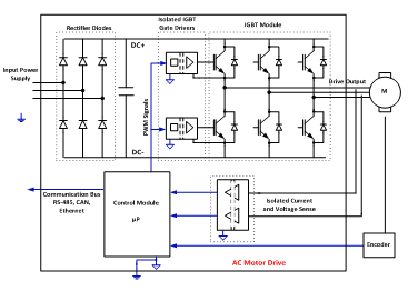
 Figure 1 Simplified block-diagram of a
typical AC motor drive
 Figure 2 Alternative architecture of an
AC motor drive
Figure 2 Alternative architecture of an
AC motor driveStep 1: Identify all of the isolators in the design and determine if they need functional, basic or reinforced isolation, depending on if and how they are placed in the path between the high-voltage circuits and human-accessible parts of the drive. The isolated gate-drivers, isolated current and voltage sense elements in Figure 1 need reinforced isolation. In Figure 2, these need only functional isolation, because reinforced isolation is provided by the digital isolators.
Step 2: Determine the system voltage. This is defined as the RMS voltage of incoming supply lines with respect to earth.
Step 3: Determine the requirements on transient overvoltage and surge voltage for the isolator based on system voltage. These requirements increase in proportion to system voltage. For reinforced isolation, the requirements are 1.6 to two times higher than for basic isolation.
Step 4: Determine the clearance requirement for the isolator based on the peak values of transient overvoltage and surge voltage determined in step No. 3. Higher clearance is required for higher voltages to prevent the breakdown of air between the two sides of the isolator. Also, for altitudes higher than 2,000m above sea level, you must multiply clearance requirements by a prescribed factor to account for lower atmospheric pressure.
Step 5: Determine the peak and RMS working voltage that the isolator is expected to endure throughout the equipment’s expected lifetime. This depends on the drive architecture as well as factors such as expected overshoots and regenerative action in the drive.
Step 6: Determine the creepage requirement for the isolator based on the RMS value of the working voltage determined in step No. 5. Creepage requirements depend on the degree of pollution present, as well as the quality of the mold compound used to package the isolator. For reinforced isolation, creepage requirements are double those for basic isolation.
Step 7: Choose an isolator that meets requirements listed from step No. 3 to step No. 6.
For a more detailed discussion of the IEC 61800-5-1 standard, see my recent white paper, “Isolation in AC motor drives: Understanding the IEC 61800-5-1 safety standard.” In this paper, I also summarize the capabilities of TI’s recent reinforced isolation products (ISO5851 and ISO5852S isolated gate drivers and ISO78xx digital isolators) in the context of IEC 61800-5-1.
Additional Resources
- Read the data sheets for TI’s ISO5851 and ISO5852S isolated gate drivers and ISO78xx digital isolators.
- Download the white paper, “High-voltage reinforced isolation: Definitions and test methodologies.”
- Jump-start design with the TI Designs Isolated IGBT Gate Driver Evaluation Platform for 3-Phase Inverter System Reference Design.
- Read other blog posts about isolation.