-
How to Simplify I2C Tree When Connecting Multiple Slaves to an I2C Master
How to Simplify I2C Tree When Connecting Multiple Slaves to an I2C Master
Rajan Arora
Electronic products such as smartphones, tablets, TVs, cars … even refrigerators and washing machines have added more and more features over the last few years to make life easier for users. To play games and monitor your health on a smartphone, you need haptic control and a touchscreen interface, which require additional sensors. Other systems in the automotive, industrial, communication markets have also added more sensors. Example systems include:
- Automotive, such as infotainment, body and advanced driver assistance systems (ADAS).
- Enterprise and communications, such as servers, network switches, and base stations.
- Industrial, such as building or factory automation, and smart grid.
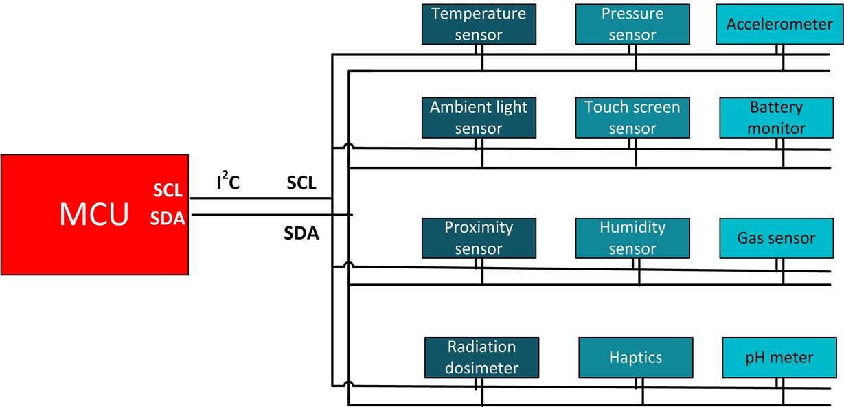
Many times these sensors communicate with the microprocessor/microcontroller (MCU) or with one another using the I2C interface. These sensors can be integrated circuits (ICs) with different functionality (for example, temperature sensor, pressure sensor, touchscreen interface), or they can be the same IC needed at multiple locations on the board (such as multiple temperature sensors). When system engineers draw a schematic of such a system, the I2C “tree” can get complicated, as shown in Figure 1. A complicated I2C tree can sometimes cause communication errors between the device and MCU, as degrading signal integrity can result in missed bits. Such an error can be pretty painful to debug, or worse, lead to product recalls.
 Figure 1 An Electronic System with
Multiple IC’s Interfacing with an MCU Using an I2C Bus
Figure 1 An Electronic System with
Multiple IC’s Interfacing with an MCU Using an I2C BusUsing I2C switches and repeaters significantly simplifies an I2C tree. You can use an I2C switch to split the I2C bus into multiple downstream I2C buses, as shown in Figure 2, splitting the I2C slaves into multiple I2C buses. You can select each downstream I2C path based on which slave needs to communicate with the MCU. In Figure 2, multiple IC’s of the same slave are split between different I2C downstream channels.
 Figure 2 Using an I2C Switch
to Split an Upstream I2C Bus into Multiple Downstream Buses
Figure 2 Using an I2C Switch
to Split an Upstream I2C Bus into Multiple Downstream BusesIf only one downstream channel is turned on at a time, there should not be any issues (unless more than 15 slaves are connected on one channel). There could be scenarios, however, where multiple paths need to be on at the same time. If multiple slaves are on the upstream I2C bus at the same time, there could be signal-integrity issues, which could result in miscommunication. Assume that each slave device will contribute ~15pF of capacitance on the I2C bus, and the overall capacitance on the bus cannot exceed the I2C specification level. Figure 3 shows how using I2C repeaters resolves such issues. The I2C repeater buffers the I2C signal, allowing the connection of multiple slaves to the downstream bus.
 Figure 3 Using Repeaters on the
Downstream I2C Bus to Improve Signal Integrity
Figure 3 Using Repeaters on the
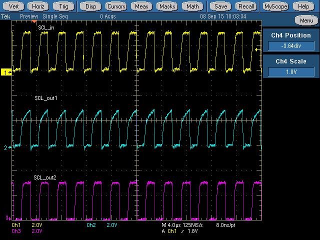
Downstream I2C Bus to Improve Signal IntegrityFigure 4 shows the clock (SCL) waveform at the input (SCL_in) and the output of the switch (SCL_out1 from Figure 2). Multiple slaves (> 25) are connected to the I2C bus, with a TCA9617B repeater added to the downstream path to improve signal quality (SCL_out2, Figure 3). As you can see from the figure, the SCL_out1 waveform has signal-integrity issues and can result in missed bits at a higher capacitance load. The SCL_out2 signal with the addition of the repeater shows much-improved signal-integrity characteristics.
Each channel may not require the addition of a repeater; you can look at the waveforms on the oscilloscope to determine this. Another issue you may see, when many slaves on the I2C bus increase capacitance, is related to pull-up strength. To improve the signal integrity caused by increasing capacitance, system engineers usually decrease the size of the pull-up resistor. However, this can cause issues pulling down the signal, as the slaves may not have strong enough pull-down. There is a limit to how much current a slave device can safely sink to ground (IOL). Adding a repeater helps increase the pull-down strength.
This technique is a useful strategy to implement into complex I2C trees and avoid any signal-integrity-related issues.
 Figure 4 The I2C SCL Signal
at the Input (SCL_in) and Output of the Switch without a Repeater (SCL_out2),
and at the Output with a Repeater on the Downstream I2C Bus
(SCL_out2)
Figure 4 The I2C SCL Signal
at the Input (SCL_in) and Output of the Switch without a Repeater (SCL_out2),
and at the Output with a Repeater on the Downstream I2C Bus
(SCL_out2)Additional Resources
- Read TI’s application note, “Maximum Clock Frequency of I2C Bus Using Repeaters.”
- Read TI’s application note, “Understanding the I2C Bus.”
- Find out more about TI’s TCA9617B repeater.
IMPORTANT NOTICE AND DISCLAIMER
TI PROVIDES TECHNICAL AND RELIABILITY DATA (INCLUDING DATASHEETS), DESIGN RESOURCES (INCLUDING REFERENCE DESIGNS), APPLICATION OR OTHER DESIGN ADVICE, WEB TOOLS, SAFETY INFORMATION, AND OTHER RESOURCES “AS IS” AND WITH ALL FAULTS, AND DISCLAIMS ALL WARRANTIES, EXPRESS AND IMPLIED, INCLUDING WITHOUT LIMITATION ANY IMPLIED WARRANTIES OF MERCHANTABILITY, FITNESS FOR A PARTICULAR PURPOSE OR NON-INFRINGEMENT OF THIRD PARTY INTELLECTUAL PROPERTY RIGHTS.
These resources are intended for skilled developers designing with TI products. You are solely responsible for (1) selecting the appropriate TI products for your application, (2) designing, validating and testing your application, and (3) ensuring your application meets applicable standards, and any other safety, security, or other requirements. These resources are subject to change without notice. TI grants you permission to use these resources only for development of an application that uses the TI products described in the resource. Other reproduction and display of these resources is prohibited. No license is granted to any other TI intellectual property right or to any third party intellectual property right. TI disclaims responsibility for, and you will fully indemnify TI and its representatives against, any claims, damages, costs, losses, and liabilities arising out of your use of these resources.
TI’s products are provided subject to TI’s Terms of Sale (www.ti.com/legal/termsofsale.html) or other applicable terms available either on ti.com or provided in conjunction with such TI products. TI’s provision of these resources does not expand or otherwise alter TI’s applicable warranties or warranty disclaimers for TI products.
Mailing Address: Texas Instruments, Post Office Box 655303, Dallas, Texas 75265
Copyright © 2023, Texas Instruments Incorporated