SSZTD40 June 2024 DP83TC817S-Q1
Automobiles have an increasing number of radar sensors to facilitate advanced driver assistance systems (ADAS), with several medium- and long-range radars to support autonomous driving up to Society of Automotive Engineers Level 2. Although this combination of radars achieves the necessary forward scanning range to operate safely and has been sufficient so far, evolving requirements for original equipment manufacturers (OEMs) in a cost-sensitive market have brought the need for new design solutions.
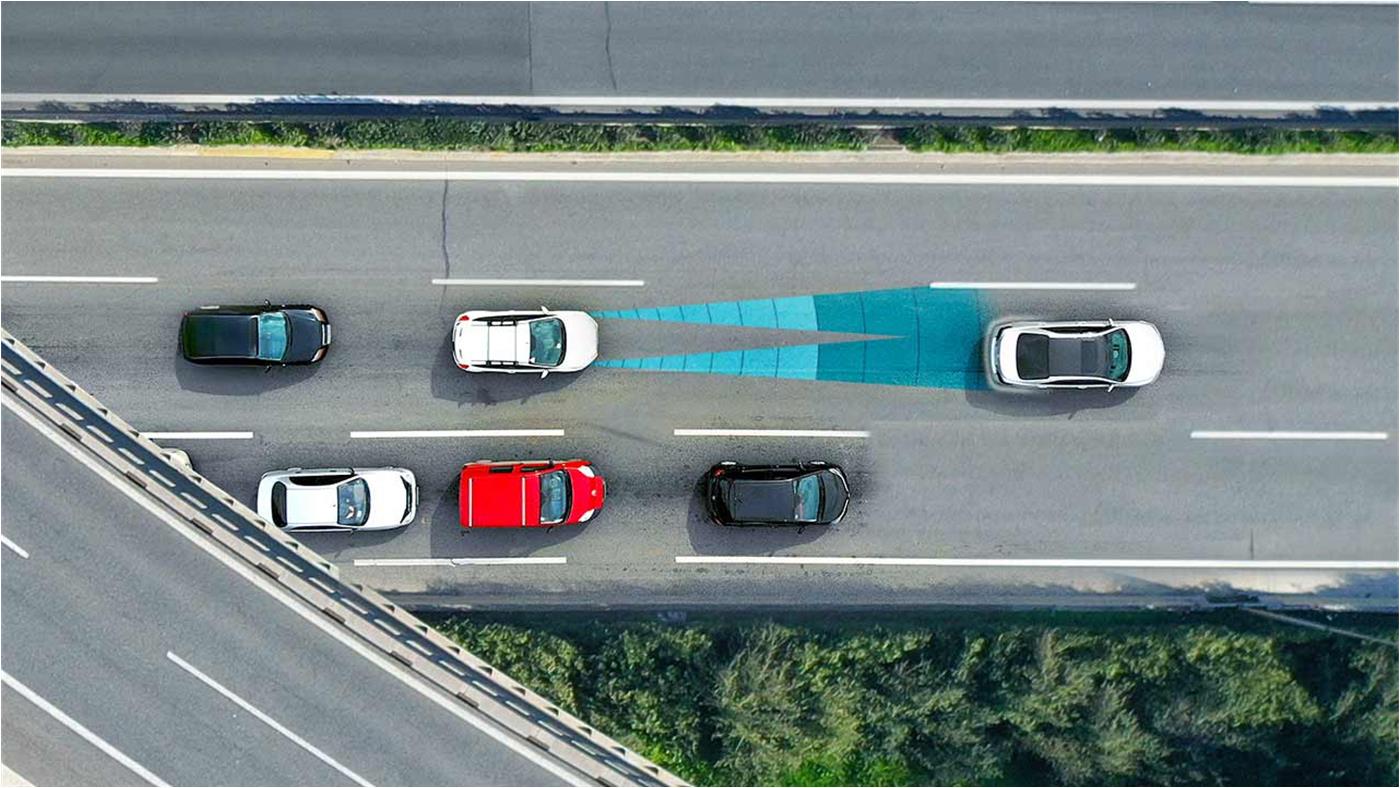
Figure 1 shows how front radar systems detect and measure distance from another vehicle.
 Figure 1 Front radar systems are designed
to detect and measure vehicles in front of them
Figure 1 Front radar systems are designed
to detect and measure vehicles in front of themNext-generation vehicles capable of Level 2 and higher autonomy levels will compete to provide these levels at increasingly lower costs to consumers, and will thus require optimized hardware and software.
Modern architectures: today’s landscape
Autonomous vehicle sensor architectures depend on the autonomy level capabilities of the vehicle. Achieving autonomous operation requires the real-time collection and processing of a large amount of sensor data. If the sensors are synchronized, special software can use the sensor data to build a virtual image of the world in front of the vehicle. With this virtual image, the ADAS microcontroller (MCU) can then compute the correct path or avoid obstacles.
Radars detect objects by emitting radio waves that are reflected by objects in its path. The radar then measures the time elapsed between the emission of the radio wave and its detection by the sensor to calculate the object’s distance. The combination of radar sensors in a typical application of a Level 2 or higher vehicle consists of three to five medium-range radar sensors supporting up to 150m of range, and a single long-range front radar supporting up to 250m of range.
Each of these radars is constantly providing data to the radar electronics control unit in frames. It is then the job of the software stack developed by OEMs and Tier 1 manufacturers to synchronize the different frames to the central clock, demanding high processing overhead. The increased data demand has thus increased the performance, power consumption, size and price requirements for the central processor.
The hardware-level synchronization of frames at the physical layer (PHY) of the Transmission Control Protocol/Internet Protocol (TCP/IP) protocol stack can drastically reduce postprocessing requirements for the central ADAS MCU. The TI DP83TC817S-Q1 Ethernet PHY transceiver can synchronize radar frames at the hardware level in both the time and frequency domains within nanoseconds across two or more radars. Figure 2 illustrates this concept.
 Figure 2 Two radars synchronized in the
time and frequency domains
Figure 2 Two radars synchronized in the
time and frequency domainsAdvantages of using hardware synchronization for ADAS autonomous operation
OEMs have adopted Ethernet as the digital backbone of large systems in zone, domain and hybrid architectures. In existing ADAS architectures, Ethernet serves as the communication link between radars and the central computing system. When positioned in radar subsystems, Ethernet PHYs send frame data to the central ADAS computer.
Advanced features on TI’s DP83TC817S-Q1 enable the recovery of the incoming central clock with the Precision Time Protocol (PTP). The device’s integrated input/output triggers the frame of the radar, providing a synchronized radar frame in time across several radars. This synchronized frame is communicated back to the radar electronic control unit. The DP83TC817S-Q1 then measures the frequency offset of the received radar frame, and in the next frame cycle corrects the radar frequency offset, synchronizing the subsequent frames in the frequency domain. Synchronization in both the time and frequency domains enables the central ADAS MCU to use the data extracted from the sensors with little postprocessing, and provides greater accuracy than software-level synchronization.
Conclusion
Ethernet PHY transceivers increase the accuracy, efficiency and range of existing radar system automotive architectures to meet the needs of OEMs and Tier 1 manufacturers by simplifying existing ADAS architectures and reducing software stack processing. The DP83TC817S-Q1 not only reduces processing at the ADAS MCU, but also reduces development cycles and increases the performance capabilities of a full radar system, allowing for architectures previously limited by cost. The combination of these features thus enables shorter cycle times for the next generation of Level 2 and higher autonomous vehicles.
Trademarks
All trademarks are the property of their respective owners.