Unlocking the possibilities of programmable logic
We often say that logic devices are the glue to every electronics design, but they are often the last parts that you might think about when choosing components for a system. There are certainly many tried-and-true standard logic devices to choose from. But designs are getting more complex, and so is the need to integrate the logic elements on the board to allow space for more functions.
Engineers are increasingly choosing programmable logic devices (PLDs), complex PLDs (CPLDs) or field-programmable gate arrays (FPGAs) to help reduce solution size, lower design and manufacturing costs, manage their supply chain, and speed time to market. There are many trade-offs to consider when designing with CPLDs or FPGAs, which support thousands of logic elements, come in various package sizes, and may require advanced software programming expertise.
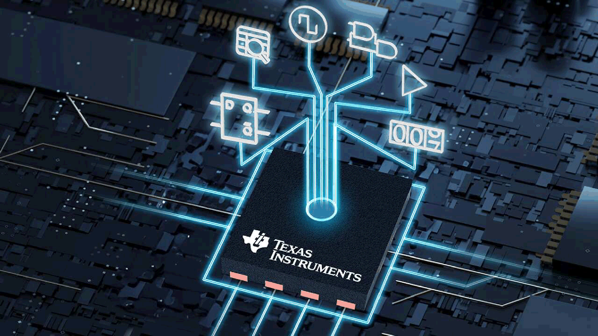
New PLDs such as those in TI’s PLD portfolio integrate dozens of sequential logic and analog functions into a single package, reducing both overall board space 90% or more and component count by at least 80% when compared to discrete logic implementations. Figure 1 illustrates several TI functions integrated into a single industry-standard package.
Configurable logic sized just right
TI’s PLD portfolio includes products that integrate logic functions, D-type flip flops, pipe delays, pattern generators, counters, delays, comparators and more. You no longer need to change hardware designs to support a different or new function or parameter; instead, you can use standard and configurable logic elements to develop solutions that provide the performance you need. TI’s PLDs require zero software development and no hardware description language coding experience.
Figure 1 outlines the configurable logic elements of the TPLD1201.
 Figure 1 TPLD1201 block diagram –
configurable logic
Figure 1 TPLD1201 block diagram –
configurable logicProgrammable logic in industry-standard packaging
Many PLDs currently on the market come in application-specific packages to support consumer electronics applications. TI PLDs use standard Joint Electron Device Engineering Council (JEDEC) leaded and nonleaded packaging options, enabling you to easily implement programmable logic in automotive and industrial applications. TI’s PLD portfolio includes leaded packages with a 0.5mm pitch, assisting you with solderability and automated optical inspection to ensure the safety and long-term reliability of your systems. The devices have an extended temperature range of –40°C to 125°C and Automotive Electronics Council (AEC) Q-100 qualification.
Configure in seconds
TI PLDs simplify the programming process by using an easy-to-use graphical interface to configure your desired circuit. After you design your logic circuit, you can temporarily configure the device for evaluation or permanently program the device for use in your end product. TI created InterConnect Studio with designers in mind, allowing you to configure TI PLDs without coding experience. InterConnect Studio helps you progress from developing and simulating in a matter of minutes and have prototypes in seconds.
Figure 2 shows a circuit design using InterConnect Studio for a power sequencing application.
 Figure 2 InterConnect Studio desktop
view of a power sequencing application using TI’s TPLD1201
Figure 2 InterConnect Studio desktop
view of a power sequencing application using TI’s TPLD1201From the menu on the left side of the GUI, you can add different components by selecting the plus sign next to the element. You can make simple drag-and-drop connections between components and fine-tune them further in the menus below the main window.
After designing the circuit and running simulation, you can easily temporarily configure the device through the TPLD programmer and evaluation modules by pressing the CONFIGURE TPLD button. Should you want to permanently program the device, there’s a check box that you can select within the menus.
Conclusion
There are numerous programmable logic solutions for designers today. TI’s PLDs are available in smaller packaging options, resulting in smaller printed circuit boards and lower production costs, ultra-low power consumption, a smaller number of logic elements, analog functionality, and easier programming when compared to more advanced programmable products. One thing is for sure – you now have more options for your programmable logic needs that meet your application requirements.
Additional resources
- Check out TI’s growing portfolio of PLDs: PLD portfolio.
- Compare TI PLD products with this parametric table.
- Read the application note, Power Sequencing With Feedback Using TI Programmable Logic Devices.
- Learn more about, Using Lookup-Tables in Programmable Logic.
- Go from concept to prototype easily with the TPLD-programmer and InterConnect Studios: https://www.ti.com/tool/TPLD-PROGRAM.
Trademarks
All trademarks are the property of their respective owners.
IMPORTANT NOTICE AND DISCLAIMER
TI PROVIDES TECHNICAL AND RELIABILITY DATA (INCLUDING DATASHEETS), DESIGN RESOURCES (INCLUDING REFERENCE DESIGNS), APPLICATION OR OTHER DESIGN ADVICE, WEB TOOLS, SAFETY INFORMATION, AND OTHER RESOURCES “AS IS” AND WITH ALL FAULTS, AND DISCLAIMS ALL WARRANTIES, EXPRESS AND IMPLIED, INCLUDING WITHOUT LIMITATION ANY IMPLIED WARRANTIES OF MERCHANTABILITY, FITNESS FOR A PARTICULAR PURPOSE OR NON-INFRINGEMENT OF THIRD PARTY INTELLECTUAL PROPERTY RIGHTS.
These resources are intended for skilled developers designing with TI products. You are solely responsible for (1) selecting the appropriate TI products for your application, (2) designing, validating and testing your application, and (3) ensuring your application meets applicable standards, and any other safety, security, or other requirements. These resources are subject to change without notice. TI grants you permission to use these resources only for development of an application that uses the TI products described in the resource. Other reproduction and display of these resources is prohibited. No license is granted to any other TI intellectual property right or to any third party intellectual property right. TI disclaims responsibility for, and you will fully indemnify TI and its representatives against, any claims, damages, costs, losses, and liabilities arising out of your use of these resources.
TI’s products are provided subject to TI’s Terms of Sale (www.ti.com/legal/termsofsale.html) or other applicable terms available either on ti.com or provided in conjunction with such TI products. TI’s provision of these resources does not expand or otherwise alter TI’s applicable warranties or warranty disclaimers for TI products.
Mailing Address: Texas Instruments, Post Office Box 655303, Dallas, Texas 75265
Copyright © 2024, Texas Instruments Incorporated