SWRA486A August 2015 – April 2017 CC1310 , CC2620 , CC2630 , CC2640 , CC2640R2F-Q1 , CC2650 , CC2650MODA
- CC26x0, CC13x0 SimpleLink™ Wireless MCU Power Management Software Development
-
CC26x0, CC13x0 SimpleLink™ Wireless MCU Power Management Software Development
- 1 Abbreviations
- 2 Power Management Introduction
- 3 TI-RTOS Power Modes
- 4 Implementation Considerations
- 5 References
- Revision History
3.3.2 Standby Exit Sequence
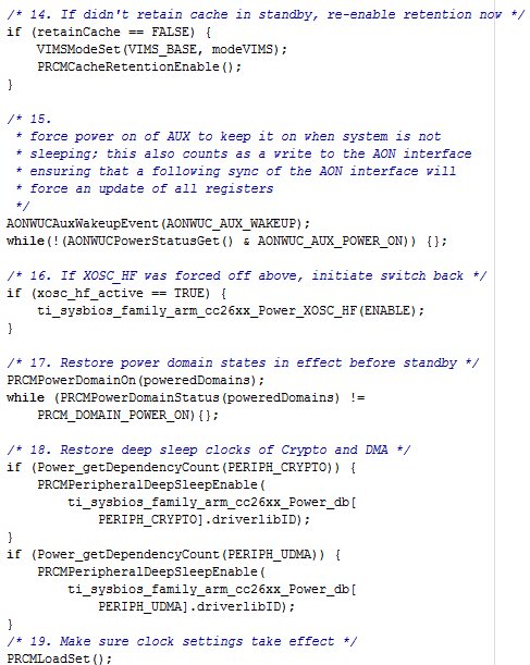
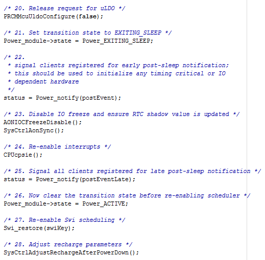
Figure 5 and Figure 6 show the code sequence for taking the device out of standby mode. A brief explanation of each step is also provided.
 Figure 5. Standby Exit Sequence, Part 1
 14. If didn't retain cache in standby, re-enable retention now— Enable cache after waking up from standby if cache retention was disabled.
15. Force power on of AUX to keep it on when system is not sleeping; this also counts as a write to the AON interface ensuring that a following sync of the AON interface will force an update of all registers— To access the OSC_DIG registers to configure the oscillators, force the auxiliary domain on after waking up from standby.
16. If XOSC_HF was forced off above, initiate switch back— Turn on the high-speed crystal oscillator if it was enabled before entering standby. For details on how to configure the high-speed crystal oscillator, see Section 4.5.1.
17. Restore power domain states in effect before standby— Turn on all power domains that were on before entering standby.
18. Restore deep sleep clocks of Crypto and DMA— Restore deep-sleep clock settings for Crypto and DMA modules as they were before entering standby.
19. Make sure clock settings take effect— Load clock settings into PRCM for them to take effect.
 Figure 6. Standby Exit Sequence, Part 2
 20. Release request for uLDO— Release the micro-LDO request to disable running on the micro-LDO when entering idle.
21. Set transition state to EXITING_SLEEP— TI-RTOS-specific code
22. Signal clients registered for early post-sleep notification; this should be used to initialize any timing critical or IO dependent hardware— Signal peripheral drivers to reinitialize their state because modules without retention lose their contents. TI-RTOS-specific code. For details on which modules have retention, see (CC13x0, CC26x0 Technical Reference Manual ).
23. Disable IO freeze and ensure RTC shadow value is updated— Open the input and output latches. Because the peripheral drivers have been reinitialized, inputs and outputs have no glitches.
24. Re-enable interrupts— Re-enable interrupts. TI-RTOS-specific code
25. Signal all clients registered for late post-sleep notification— The peripheral drivers do not use this notification. (TI-RTOS-specific code)
26. Now clear the transition state before re-enabling scheduler— TI-RTOS-specific code
27. Re-enable Swi scheduling— TI-RTOS-specific code
28. Adjust recharge parameters— Adjust the recharge settings to optimize power consumption the next time the application enters standby mode.