SWRA640H December 2018 – May 2024 CC1310 , CC1312R , CC1314R10 , CC1350 , CC1352P , CC1352R , CC1354P10 , CC1354R10 , CC2620 , CC2630 , CC2640 , CC2640R2F , CC2640R2F-Q1 , CC2642R , CC2642R-Q1 , CC2650 , CC2652P , CC2652R , CC2652R7 , CC2652RB , CC2652RSIP , CC2674P10 , CC2674R10
- 1
- Abstract
- Trademarks
- 1 Reference Design
- 2 Front-End Configurations
- 3 Schematic
- 4 PCB Layout
- 5 Antenna
- 6 Crystal Tuning
- 7 TCXO Support
- 8 Integrated Passive Component (IPC)
- 9 Optimum Load Impedance
- 10PA Table
- 11Power Supply Configuration
- 12Board Bring-Up
- 13References
- 14Revision History
5.2.1 Dual-Band Antenna Match Example: 863-928 MHz and 2.4 GHz
This example is based on LaunchPad-CC1352P1.
- Assemble LHIGH: 0Ω and CLOW : 0Ω; CHIGH: NC and LLOW : NC
- Measure initial impedance with a network analyzer (VNA) at the
low-band (868MHz) and high-band (2440MHz)
- 868MHz: 54 + j30, VSWR: 1.78:1
- 2.44GHz: 14 - j32, VSWR: 5.05:1 (This is not required at this stage but included for documentation purposes to note the delta).
- Match the low-band with only the CLOW and
LLOW components
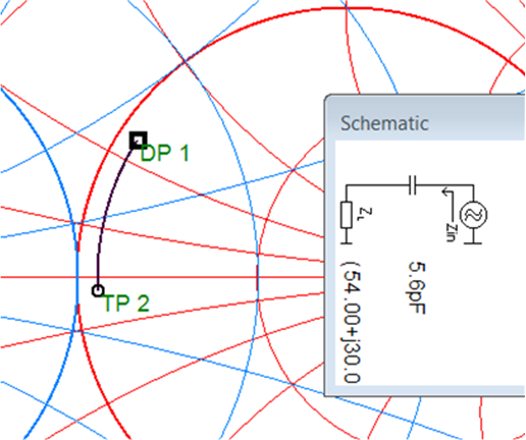
- CLOW: 5.6pF and LLOW: NC; see Figure 5-3
 Figure 5-3 Matching the Low-Band
With CLOW: 5.6pF and LLOW: NC
 - Confirm the low-band is matched by measuring the impedance
again:
- 868MHz: 42 + j2, VSWR: 1.18:1. Good match at the low-band
- 2.44GHz: 16+j34, VSWR: 5.38:1
- Match the high-band with only the CHIGH and
LHIGH components
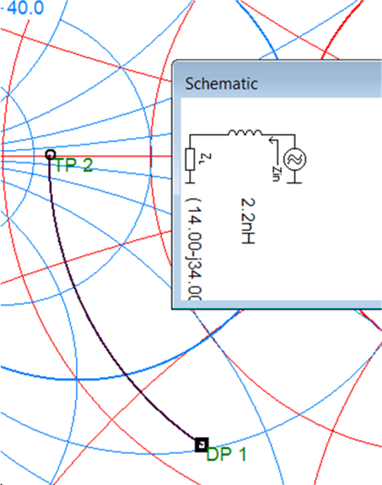
- LHIGH : 2.2nH and CHIGH: NC; see Figure 5-4
 Figure 5-4 Matching the High-Band
With an Ideal Value of LHIGH: 2.2nH and CHIGH:
NC
 - LHIGH : 2.2nH was not sufficient when measured and a value of 3.3nH was used instead. The antenna match components are based on ideal components with no parasitics. The match is not ideal but the CHIGH component could not be used due to the impedance position in the Smith chart.
- Measure final impedance with a network analyzer (VNA) at the
low-band (868MHz) and high-band (2440MHz),
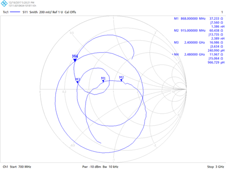
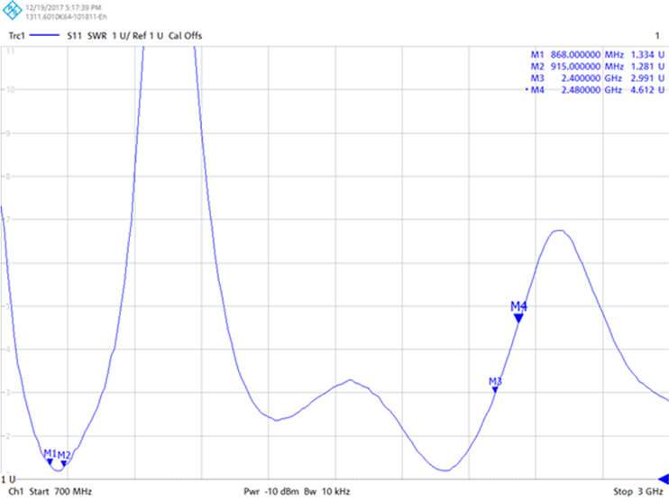
- 868MHz: 37 + j8, VSWR: 1.36:1 Good match at the low-band
- 2.44GHz: 16+j8, VSWR: 3.18:1 Reasonable match at the
high-band but would prefer VSWR < 2.00:1; see Figure 5-5 and Figure 5-6.
 Figure 5-5 Smith Chart
With Final Match Values of LHIGH: 3.3nH and
CLOW: 5.6pF
 Figure 5-6 VSWR Chart
With Final Match Values of LHIGH: 3.3nH and
CLOW: 5.6pF
- With the matching components, the antenna match was improved
by:
- 868MHz: VSWR: 1.78:1 –> 1.36:1
- 2.44GHz: VSWR: 5.05:1 –> 3.18:1
The example shown above used a low-band of 868MHz but a main requirement of the LaunchPad-CC1352P-1 was for good operation for the complete 863 – 928MHz band since it was important to cover both ETSI (863-870MHz) and FCC bands (902-928MHz). The antenna length on CC1352P1 has a natural resonance of approximately 900MHz with no matching components.
If the performance at 2.44GHz is more important than supporting both 868MHz and 915MHz ISM bands, then the length of the antenna can be increased so the natural resonance will be around 813MHz (2440MHz/3). This would give very good performance at 868 MHz and 2.4GHz but the 915MHz band would suffer. A common antenna match for dual-bands is a compromise of performance between the high-band and low-band.