SWRA640H December 2018 – May 2024 CC1310 , CC1312R , CC1314R10 , CC1350 , CC1352P , CC1352R , CC1354P10 , CC1354R10 , CC2620 , CC2630 , CC2640 , CC2640R2F , CC2640R2F-Q1 , CC2642R , CC2642R-Q1 , CC2650 , CC2652P , CC2652R , CC2652R7 , CC2652RB , CC2652RSIP , CC2674P10 , CC2674R10
- 1
- Abstract
- Trademarks
- 1 Reference Design
- 2 Front-End Configurations
- 3 Schematic
- 4 PCB Layout
- 5 Antenna
- 6 Crystal Tuning
- 7 TCXO Support
- 8 Integrated Passive Component (IPC)
- 9 Optimum Load Impedance
- 10PA Table
- 11Power Supply Configuration
- 12Board Bring-Up
- 13References
- 14Revision History
6.1 CC13xx/CC26xx Crystal Oscillators
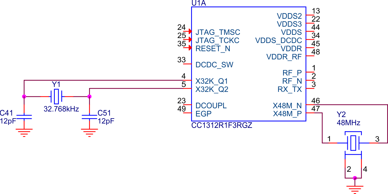
The CC13xx/CC26xx devices have two crystal oscillators as shown in Figure 6-1. The high frequency crystal oscillator (HFXOSC), running at 24MHz for CC13x0/CC26x0 and 48MHz for CC13x2/CC26x2, is mandatory to operate the radio. The low frequency crystal oscillator (LFXOSC) is used for RTC timing and only required when accurate RTC timing is necessary, for example for synchronous protocols such as Bluetooth Low Energy. For more details, please see The Crystal Selection Guide.
 Figure 6-1 CC1312R With 32kHz and 48MHz Crystals
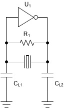
Both crystal oscillators are pierce type oscillators are shown in Figure 6-2. In this type of oscillator, the crystal and the load capacitors form a pi-filter providing a 180° phase shift to the internal amplifier keeping the oscillator locked at the specified frequency. For this frequency to be correct, the load capacitance must be dimensioned properly based on the crystal´s capacitive load (CL) parameter.
 Figure 6-2 Pierce-Type Oscillator
A key difference between the oscillators is that the high frequency oscillator has internal variable load capacitance inside the IC and does in most cases not require external load capacitors. For details on when it is required to use external capacitors instead of the internal variable load capacitance, see Section 3.1.1. The low frequency oscillator on the other hand needs to have external capacitors to operate properly.