TIDT334 September 2023 UCD3138
3.1 Load Transients
Load transient response waveforms are shown in the following figures.
Channel 1 is the AC portion of the output voltage, channel 2 is one of the primary drive signals, channel 3 is the primary resonant current, and channel 4 is load current.
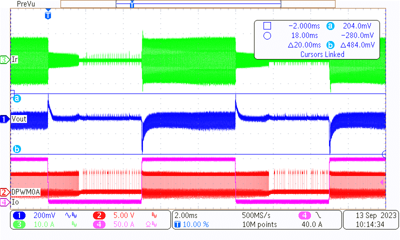 Figure 3-1 Load Transient of 400-V, 0% -100%,
5 ms-5 ms, 2.5-A/µs Slew Rate
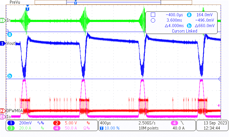 Figure 3-3 Load Transient of 400-V, 0%-150%,
1 ms-0.1 ms, 2.5-A/µs Slew Rate
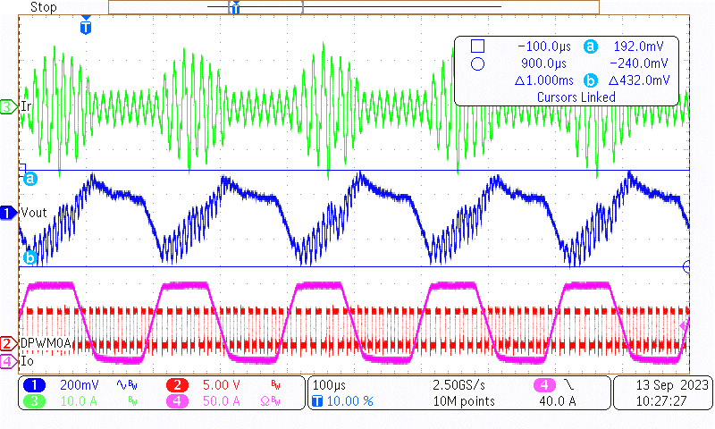 Figure 3-5 Load Transient of 380-V, 0%-100%,
0.1 ms-0.1 ms, 2.5-A/µs Slew Rate
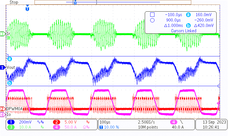 Figure 3-7 Load Transient of 420-V, 0%-100%,
0.1 ms-0.1 ms, 2.5-A/µs Slew Rate
 Figure 3-2 Load Transient of 400-V, 0%-100%,
0.1 ms-0.1 ms, 2.5-A/µs Slew Rate
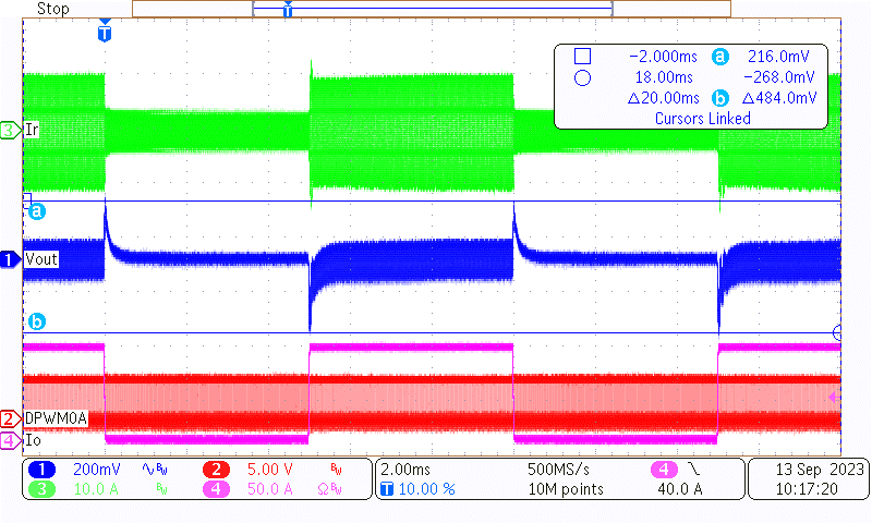 Figure 3-4 Load Transient of 380-V, 0%-100%,
5 ms-5 ms, 2.5-A/µs Slew Rate
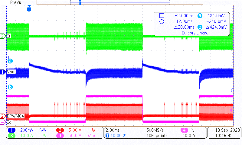 Figure 3-6 Load Transient of 420-V, 0%-100%,
5 ms-5 ms, 2.5-A/µs Slew Rate