TIDU858C March 2015 – May 2021
- Description
- Resources
- Features
- Applications
- 5
- 1System Description
- 2Design Features
- 3Circuit Design and Component Selection
- 4Testing
- 5Design Files
- 6References
- Trademarks
- 7About the Author
- 8Revision History
4.1 Test Setup and Connection Diagram
The setup shown in Figure 4-1 consists of a DC supply with current limit used for accurately powering the TIDA-00420 board. The DC supply is also used as a programmable voltage source for testing the measurement accuracy of captured samples of the interface board. The board is interfaced to the GUI for processing the samples and configuring the ADC.
 Figure 4-1 Test Setup Layout
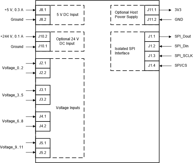
Figure 4-2 shows the connection diagram used for board testing. Connectors are provided to connect the AC or DC voltage inputs. Screw type terminals are provided to connect the DC supply communication interface connector (header-male type) to the ADC, and then to the host.
 Figure 4-2 Connections for Performance Testing