TIDUEX1A December   2020  – March 2021


  1.   Description
  2.   Resources
  3.   Features
  4.   Applications
  5.   5
  6. 1System Description
    1. 1.1 Key System Specifications
  7. 2System Overview
    1. 2.1 Block Diagram
    2. 2.2 Design Considerations
    3. 2.3 Highlighted Products
      1. 2.3.1 TMP117 – High-accuracy, low-power, digital temperature sensor
      2. 2.3.2 System Design Theory
        1. 2.3.2.1 System Accuracy
  8. 3Hardware, Software, Testing Requirements, and Test Results
    1. 3.1 Hardware
    2. 3.2 Software
      1. 3.2.1 SysConfig
      2. 3.2.2 Graphical User Interface (GUI)
        1. 3.2.2.1 Launching and Running the Software
        2. 3.2.2.2 Using the GUI
          1. 3.2.2.2.1 Home Tab
          2. 3.2.2.2.2 Data Capture Tab
          3. 3.2.2.2.3 EVM Setup Tab
          4. 3.2.2.2.4 Configuration Tab
          5. 3.2.2.2.5 Register Tab
          6. 3.2.2.2.6 Collateral Tab
    3. 3.3 Testing and Results
      1. 3.3.1 Test Setup
        1. 3.3.1.1 System Accuracy
      2. 3.3.2 Test Results
  9. 4Design and Documentation Support
    1. 4.1 Design Files
      1. 4.1.1 Schematics
      2. 4.1.2 BOM
    2. 4.2 Tools and Software
      1. 4.2.1 PCB Layout Recommendations
      2. 4.2.2 Software Files
    3. 4.3 Documentation Support
    4. 4.4 Support Resources
    5. 4.5 Trademarks
  10. 5Revision History

PCB Layout Recommendations

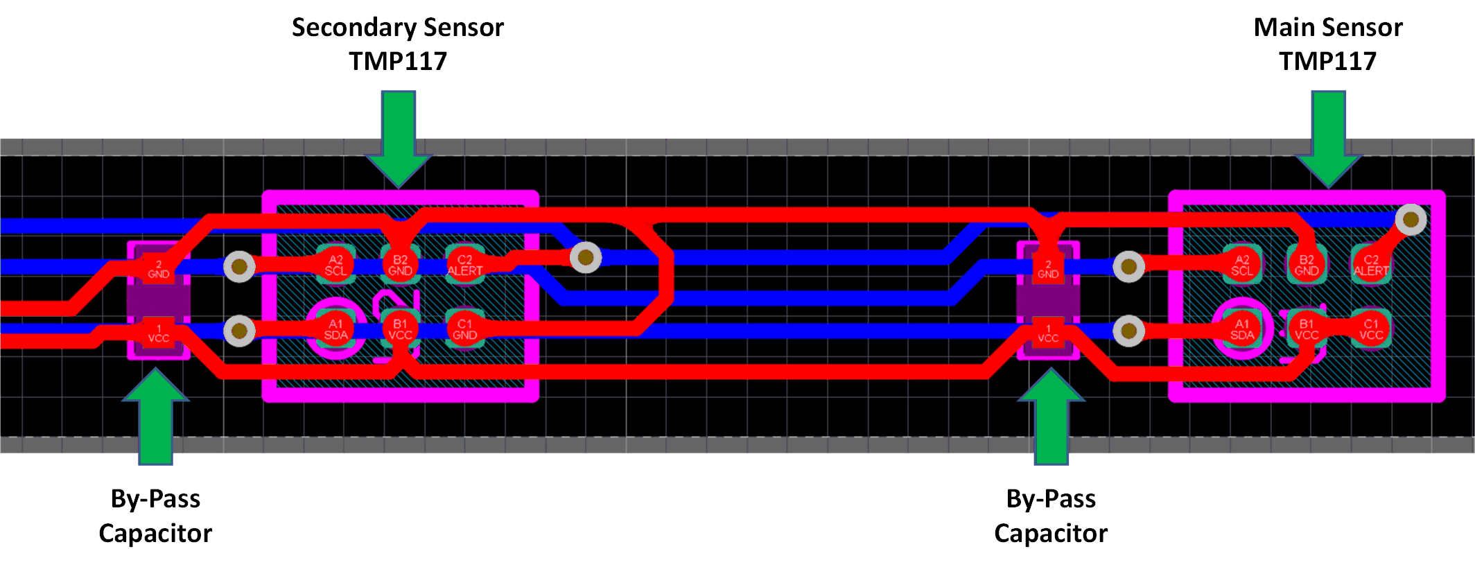
The Hearables Body Temperature Monitor Flex PCB Strip was designed with a thin 2-layer flex PCB with a minimalistic profile. This is to allow for easy integration into small hearable devices as well as to have a fast thermal response time. For general recommendations for flex PCB designs, designers should consult with the flex board manufacturer. It is important that this aspect be considered to minimize potential damage to the board traces. While this design does not integrate any stiffener to maximize flexibility, a stiffener should be used on portions that are not intended to bend. The routing of the TMP117 devices was intended to keep the minimal width of the flex board while still being able to access all functions of the device. Small 01005 size decoupling capacitors were also used to keep the minimal profile. Figure 4-1 shows the routing of the TMP117 devices on the flex board.
GUID-20200810-CA0I-J6TF-SMT0-M3DZGZ3Q610J-low.gif Figure 4-1 TMP117 Layout