TIDUEY9 April   2021


  1.   Description
  2.   Resources
  3.   Features
  4.   Applications
  5.   5
  6. 1System Description
  7. 2System Overview
    1. 2.1 Block Diagram
    2. 2.2 Design Considerations
    3. 2.3 Highlighted Products
      1. 2.3.1 LP8770
        1. 2.3.1.1 Safety Features
          1. 2.3.1.1.1 Window Watchdog
          2. 2.3.1.1.2 Voltage Monitoring
      2. 2.3.2 AWR1843/xWR6843 mmWave Sensor Solution
    4. 2.4 System Design
      1. 2.4.1 Hardware Block Diagram
      2. 2.4.2 Software Components
        1. 2.4.2.1 Secondary Bootloader (SBL)
        2. 2.4.2.2 mmWaveLink APIs
        3. 2.4.2.3 mmWave Safety Diagnostic Library (SDL)
        4. 2.4.2.4 mmWave SDK Software Block Diagram
  8. 3Hardware, Software, Testing Requirements, and Test Results
    1. 3.1 Hardware Requirements
    2. 3.2 Test Setup
    3. 3.3 Test Results
  9. 4Design and Documentation Support
    1. 4.1 Design Files
      1. 4.1.1 Schematics
      2. 4.1.2 BOM
    2. 4.2 Tools and Software
    3. 4.3 Documentation Support
    4. 4.4 Support Resources
    5. 4.5 Trademarks
  10. 5About the Author

Test Results

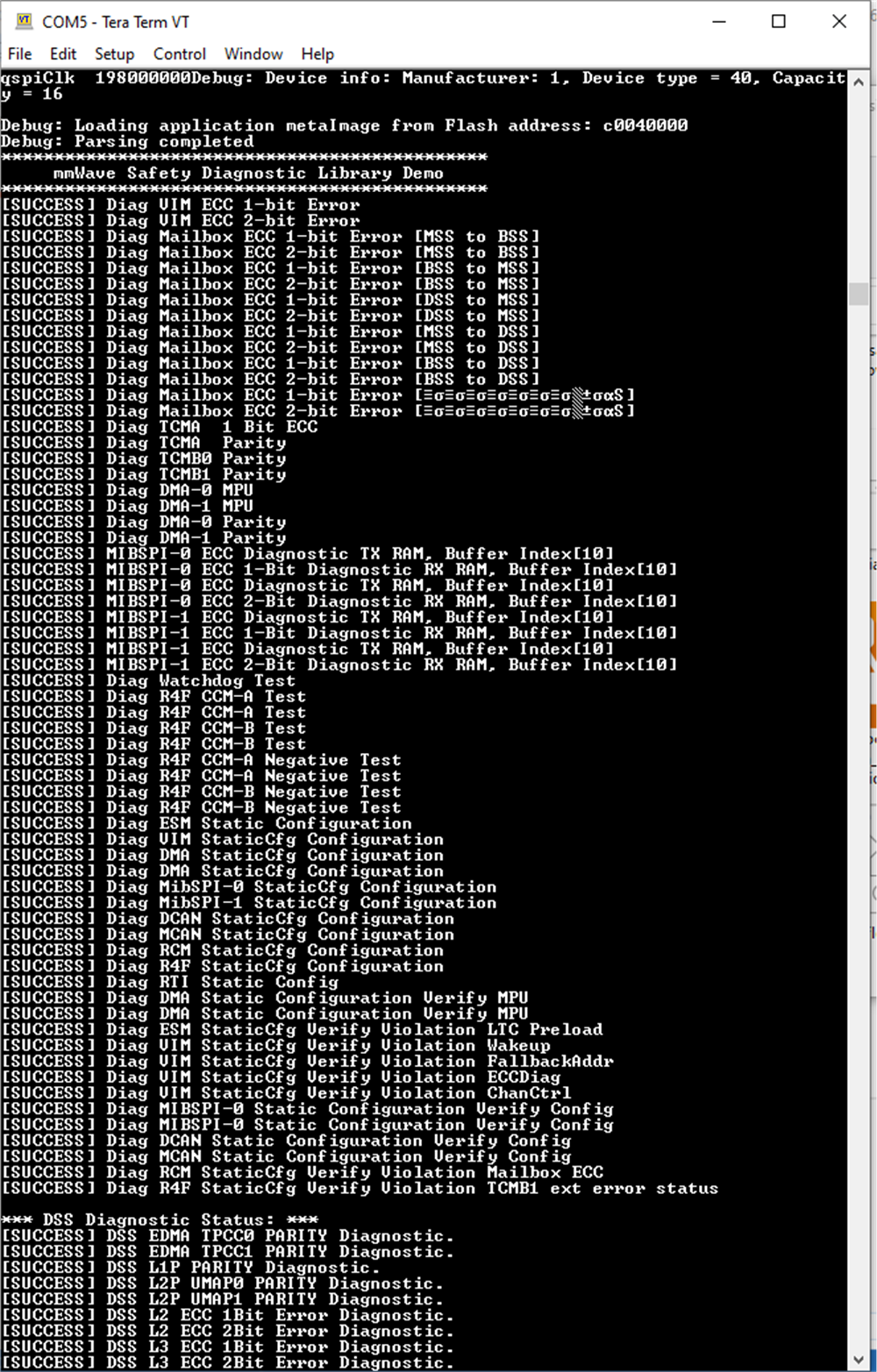
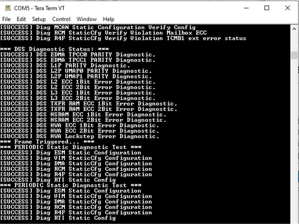
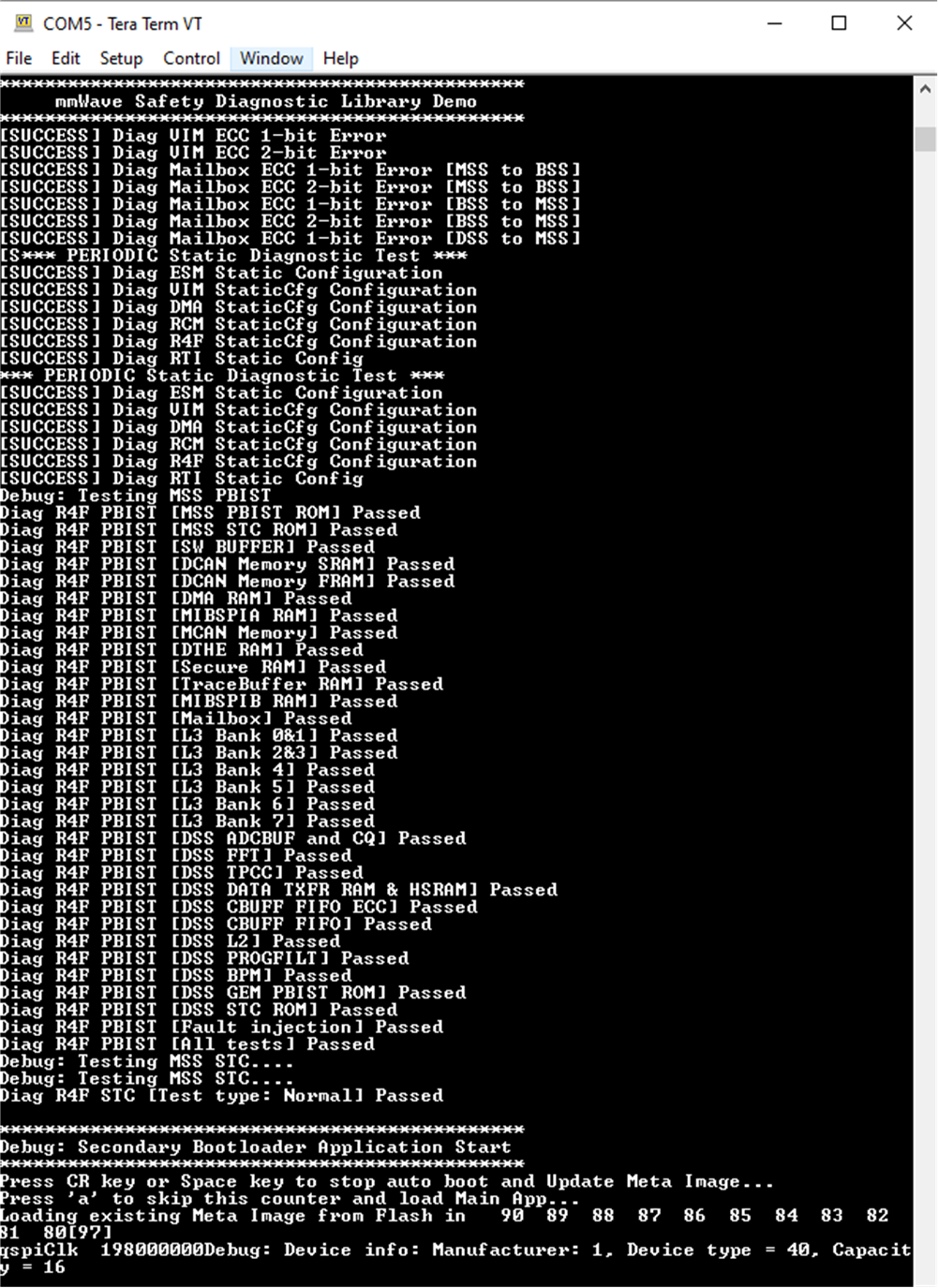
AWR1843BOOST or xWR6843ISK is connected with the PC over USB cable. SBL image is flashed first then the main application. Refer Getting started document in the software package for exact steps to execute this application.

Figure 3-3, Figure 3-4, and Figure 3-5 show the test result of Diagnostic test result performed by SBL as well as Main application.
GUID-20210312-CA0I-CBKJ-CSSF-8GVTDLGDCSSR-low.pngFigure 3-3 Diagnostic Test Results 1
GUID-20210312-CA0I-N57S-GQSH-XTJCXHTL8FND-low.pngFigure 3-4 Diagnostic Test Results 2
GUID-20210312-CA0I-MKLK-KPL7-TPBP0ZGVNFGW-low.png Figure 3-5 Diagnostic Test Results 3