TIDUEY9 April   2021


  1.   Description
  2.   Resources
  3.   Features
  4.   Applications
  5.   5
  6. 1System Description
  7. 2System Overview
    1. 2.1 Block Diagram
    2. 2.2 Design Considerations
    3. 2.3 Highlighted Products
      1. 2.3.1 LP8770
        1. 2.3.1.1 Safety Features
          1. 2.3.1.1.1 Window Watchdog
          2. 2.3.1.1.2 Voltage Monitoring
      2. 2.3.2 AWR1843/xWR6843 mmWave Sensor Solution
    4. 2.4 System Design
      1. 2.4.1 Hardware Block Diagram
      2. 2.4.2 Software Components
        1. 2.4.2.1 Secondary Bootloader (SBL)
        2. 2.4.2.2 mmWaveLink APIs
        3. 2.4.2.3 mmWave Safety Diagnostic Library (SDL)
        4. 2.4.2.4 mmWave SDK Software Block Diagram
  8. 3Hardware, Software, Testing Requirements, and Test Results
    1. 3.1 Hardware Requirements
    2. 3.2 Test Setup
    3. 3.3 Test Results
  9. 4Design and Documentation Support
    1. 4.1 Design Files
      1. 4.1.1 Schematics
      2. 4.1.2 BOM
    2. 4.2 Tools and Software
    3. 4.3 Documentation Support
    4. 4.4 Support Resources
    5. 4.5 Trademarks
  10. 5About the Author

Software Components

This application showcases Diagnostic and Monitoring feature of mmWave sensor. It uses SafeTI Diagnostic Library (SDL) for diagnostic test implementation and mmWaveLink to configure monitoring on RF front end.

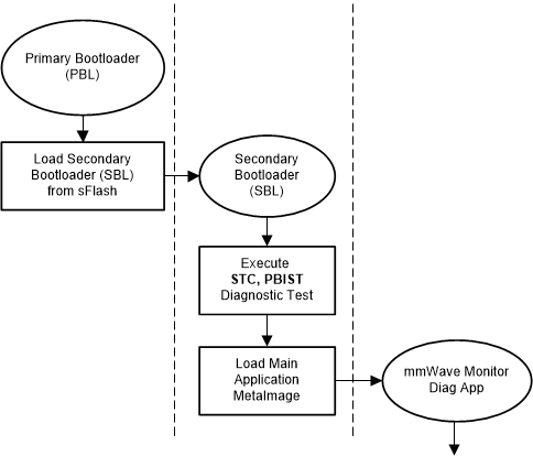
In this reference design application, few Diagnostic tests are done in secondary bootloader (SBL) at MSS core. At the end of these tests, SBL loads the main application to MSS & DSS RAM location reading MetaImage from sFlash.

GUID-20210305-CA0I-LKQP-54JD-9BPSN31KBDFJ-low.gif

Figure 2-6 Application Control Flow Diagram

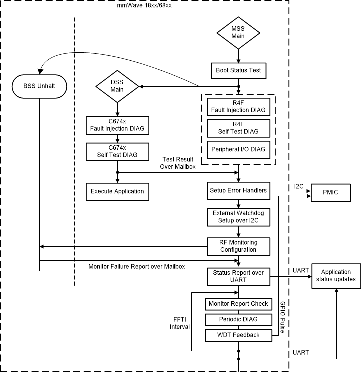
Figure 2-7 shows high level of flow diagram of main application which contains MSS and DSS images. Diagnostic and Monitor test status from sensor are sent over UART to PC.

GUID-20210225-CA0I-NTVN-K4JR-0BV4WHR0LJWR-low.gif

Figure 2-7 DIAG and Monitor App Flow Diagram