TIDUEZ1 March 2021
- Description
- Resources
- Features
- Applications
- 5
- 1System Description
-
2System Overview
- 2.1 Block Diagram
- 2.2
Design Considerations
- 2.2.1 Multichannel SSR with Independent Isolation Between SSR Channels
- 2.2.2 Design Challenge With Single Isolation
- 2.2.3 Multichannel SSR Drive With Single Isolation Multichannel Digital Isolator
- 2.2.4 Need of High-Impedance Voltage Translator
- 2.2.5 Design to Minimize Cross-Coupling and MOSFET Gate Pick up Due to Other SSR Switching
- 2.2.6 Schematic: Design of Gate-Drive Circuit
- 2.2.7 Schematic: Digital Isolator Circuit
- 2.2.8 Schematic: 3.3 V to 10V_ISO, 5V_ISO Power Supply
- 2.3 Highlighted Products
- 3Hardware, Software, Testing Requirements, and Test Results
- 4Design and Documentation Support
- 5About the Author
2.2.2 Design Challenge With Single Isolation
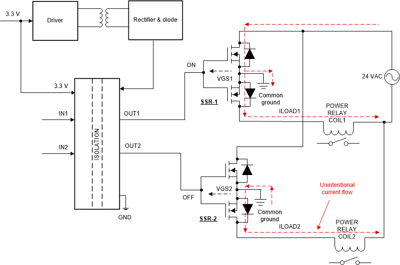
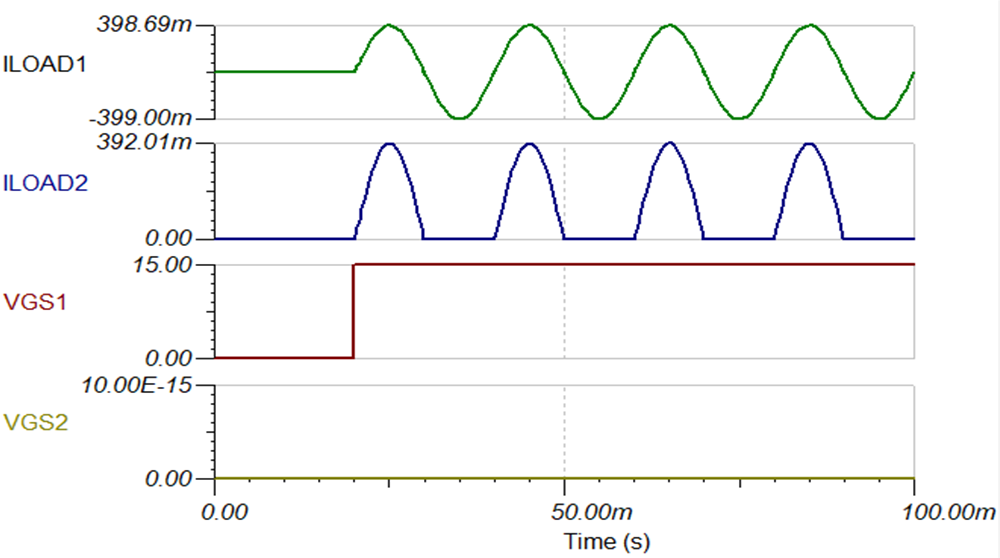
Figure 2-4 shows the configuration having SSR-1 and SSR-2 MOSFETs using a common ground for the gate drive at secondary of the isolator. Assume that SS-1 is turned on and SSR-2 is kept off. When the SSR-1 is turned on, the common ground at the gate drive causes circulating current through the common ground and the anti-parallel diode of the low-side MOSFET of SSR-2 during the negative half cycle of 24-V AC power supply. The unintentional half wave current flows through load (ILOAD2) connected through SSR-2 (despite being turned OFF), will turn on the SSR-2 load relay in the negative half cycle of input 24-V AC supply. Figure 2-4 shows the unintentional half wave rectified current waveform.
 Figure 2-4 Unintentional Current Flow in Driving
Multiple SSR With Common Ground Gate-Drive Supply
  Figure 2-5 Half-Wave Rectified Current in Driving Multiple SSR With Common Ground Gate-Drive
Supply