TIDUEZ1 March 2021
- Description
- Resources
- Features
- Applications
- 5
- 1System Description
-
2System Overview
- 2.1 Block Diagram
- 2.2
Design Considerations
- 2.2.1 Multichannel SSR with Independent Isolation Between SSR Channels
- 2.2.2 Design Challenge With Single Isolation
- 2.2.3 Multichannel SSR Drive With Single Isolation Multichannel Digital Isolator
- 2.2.4 Need of High-Impedance Voltage Translator
- 2.2.5 Design to Minimize Cross-Coupling and MOSFET Gate Pick up Due to Other SSR Switching
- 2.2.6 Schematic: Design of Gate-Drive Circuit
- 2.2.7 Schematic: Digital Isolator Circuit
- 2.2.8 Schematic: 3.3 V to 10V_ISO, 5V_ISO Power Supply
- 2.3 Highlighted Products
- 3Hardware, Software, Testing Requirements, and Test Results
- 4Design and Documentation Support
- 5About the Author
2.2.7 Schematic: Digital Isolator Circuit
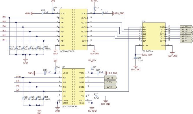
Figure 2-11 shows the digital isolator circuit for the 10-channel SSR. To get ten SSR channels, a 6-channel (ISO7760) and a 4-channel (ISO7740) digital isolator is used. For any other number of SSR channels different combinations of digital isolators can be used. For example an 8-channel SSR circuit can be created using two 4-channel digital isolators (ISO7740). A 9-channel SSR can be realized using one 6-channel digital isolator (ISO7760) and one 3-channel digital isolator (ISO7730). The IN1-IN10 are the relay turn on and turn off control signal from the microcontroller. For example, to turn on the relay connected to SSR channel 1 (COIL-1), keep IN1 in the logic high state. To turn the relay off, keep IN1 in logic low state.
In the case where there is a requirement to route a diagnosis signal from the relay side to the MCU side, a digital isolator with one reverse channel can be used. For example, an ISO7761 device provides five forward-direction channels and one reverse-direction channel.
If the input power or signal is lost, the default output is high for ISO7760 devices without suffix F and low for devices with suffix F. This reference design uses the device with suffix F (ISO7760F and ISO7740F) to make sure that in the absence of input-side powers supply, all the SSR are turned off. The 100-kΩ pulldown resistors at the input of the digital isolator is optional and may not be needed in a system-level board design. The resistor at the EN pin of ISO7740 is not populated, so as to enable the outputs of ISO7740. The 0-Ω resistors at the VCC terminals of digital isolator is a placeholder for current consumption measurement, if needed.
The reference design uses the TPL7407LA device as the low-side switch for 7 channels, connected at the output of the digital isolator. The remaining 3 channels of SSR use a separate NPN transistor.
 Figure 2-11 Digital Isolator Interface for Ten
Channel SSR