TIDUF17 November 2022 TMS320F2800152-Q1 , TMS320F2800153-Q1 , TMS320F2800154-Q1 , TMS320F2800155 , TMS320F2800155-Q1 , TMS320F2800156-Q1 , TMS320F2800157 , TMS320F2800157-Q1
- Description
- Resources
- Features
- Applications
- 5
- 1System Description
-
2System Overview
- 2.1 Block Diagram
- 2.2 Design Considerations
- 2.3 Highlighted Products
- 2.4 System Design Theory
- 3Hardware, Software, Testing Requirements, and Test Results
- 4Design and Documentation Support
3.3.2.2 Running the Application
Run the code by going to Run → Resume or clicking the Resume button in the tool bar. Check the following:
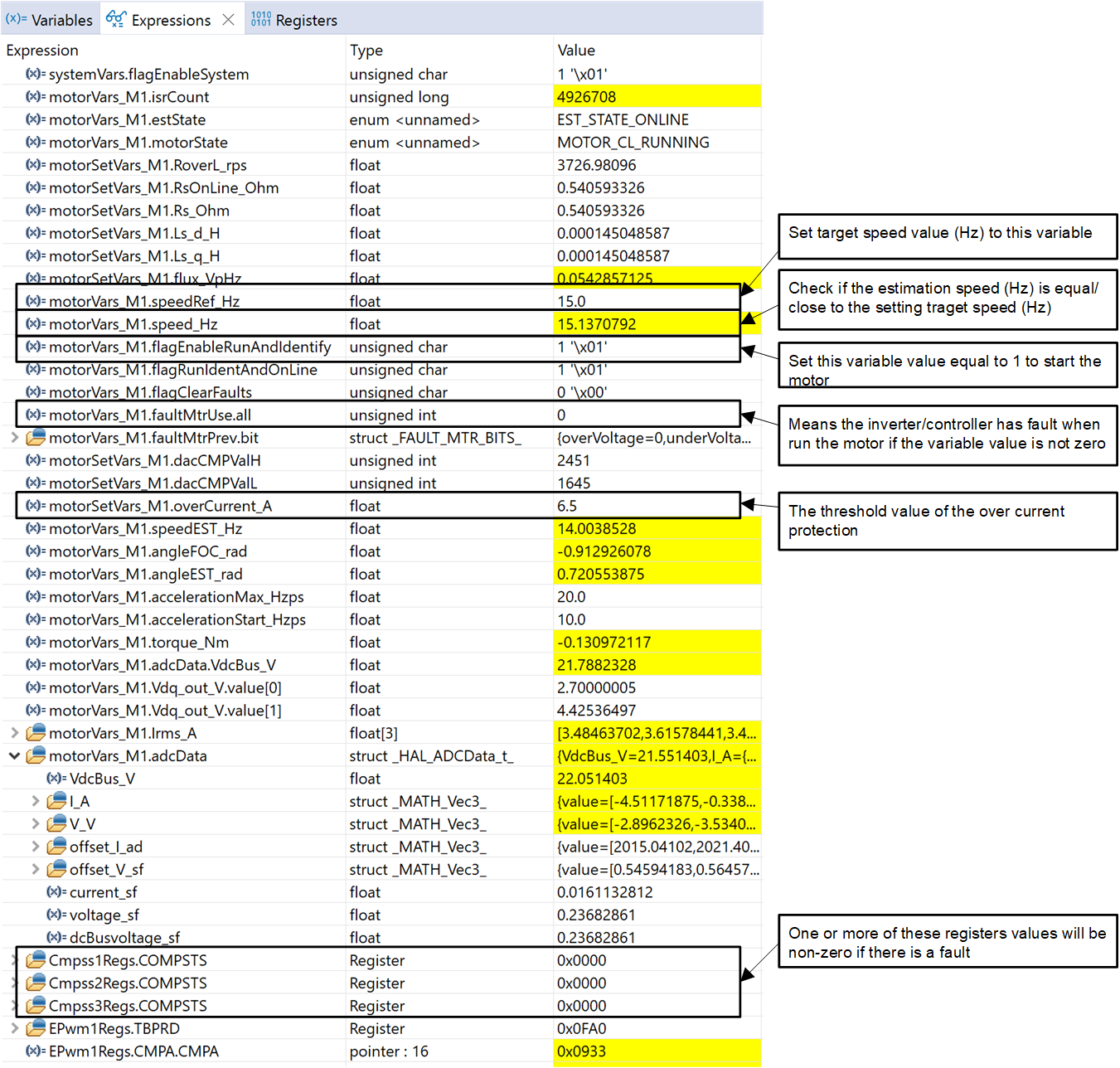
- systemVars.flagEnableSystem needs to be set to 1 after a fixed time, meaning the offset calibration has been done. The fault flags, motorVars_M1.faultMtrUse.all, should be equal to 0. Set the variable motorVars_M1.flagEnableRunAndIdentify to 1.
- The motor will run with v/f open loop. Tune the v/f profile parameters in
user_mtr1.h as below according to the specification of the motor if
the motor doesn't spin
smoothly.
#define USER_MOTOR1_FREQ_LOW_Hz (10.0f) // Hz #define USER_MOTOR1_FREQ_HIGH_Hz (200.0f) // Hz #define USER_MOTOR1_VOLT_MIN_V (10.0f) // Volt #define USER_MOTOR1_VOLT_MAX_V (200.0f) // Volt -
After that, the motor spins with a setting speed in the variable motorVars_M1.speedRef_Hz, check the value of motorVars_M1.speed_Hz in Expressions window, the values of these two variables should be very close as shown in Figure 3-10.
- Use the DATALOG module with the CCS Graph utility to check the current
sensing signals. Go to Tools → Graph → Dual Time to launch
the tool and use the Import button to navigate to the file <SDK
install
location>\solutions\tidm_02012_ecompressor\common\debug\motor_datalog_fp2.graphProp.
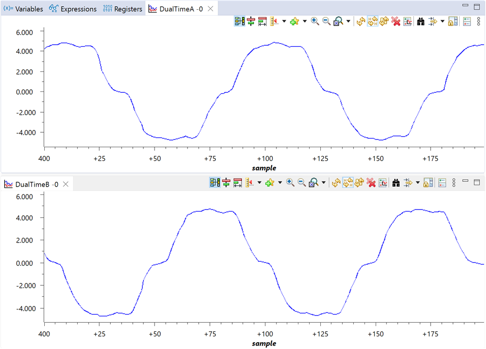
Click OK and the graphed current readings should be displayed as shown in
Figure 3-11. The code below shows how the variables to be logged are configured in
sys_main.h. For more details about about the DATALOG module, see the
Motor Control SDK Universal Project and Lab User's
Guide.
// set datalog parameters datalogObj->iptr[0] = &motorVars_M1.adcData.I_A.value[0]; datalogObj->iptr[1] = &motorVars_M1.adcData.I_A.value[1]; - Verify the over current fault protection by decreasing the value of the variable motorVars_M1.overCurrent_A, the over current protection is implemented by the CMPSS modules. The over current fault will be triggered if the motorVars_M1.overCurrent_A is set to a value less than the motor phase current actual value. When the fault occurs the PWM output will be disabled, the motorVars_M1.flagEnableRunAndIdentify will be cleared to 0, and the motorVars_M1.faultMtrUse.all will be set to 0x10 (16) as shown in Figure 3-10.
- Set the variable motorVars_M1.flagEnableRunAndIdentify to 0 to stop the motor. Terminate the debug session and power off the power supply to the inverter board.
 Figure 3-10 Build Level 2 Variables in the
Expressions View
Figure 3-10 Build Level 2 Variables in the
Expressions ViewThe Graph tool can be used to display the DATALOG buffers.
 Figure 3-11 Build Level 2 Data Logged
Current Readings in the CCS Graph Tool
Figure 3-11 Build Level 2 Data Logged
Current Readings in the CCS Graph ToolThe over current fault will trip the PWM output and also be reflected in the fault flag variables.
 Figure 3-12 Build Level 2 Over Current
Protection Check in the Expressions View