TIDUF52 December 2023 MSPM0L1303 , MSPM0L1304 , MSPM0L1305 , MSPM0L1306 , MSPM0L1343 , MSPM0L1344 , MSPM0L1345 , MSPM0L1346
- 1
- Description
- Resources
- Features
- Applications
- 6
- 1System Description
- 2System Overview
- 3Hardware, Software, Testing Requirements, and Test Results
- 4Design and Documentation Support
- 5About the Author
3.2.4 Smoke Detector GUI
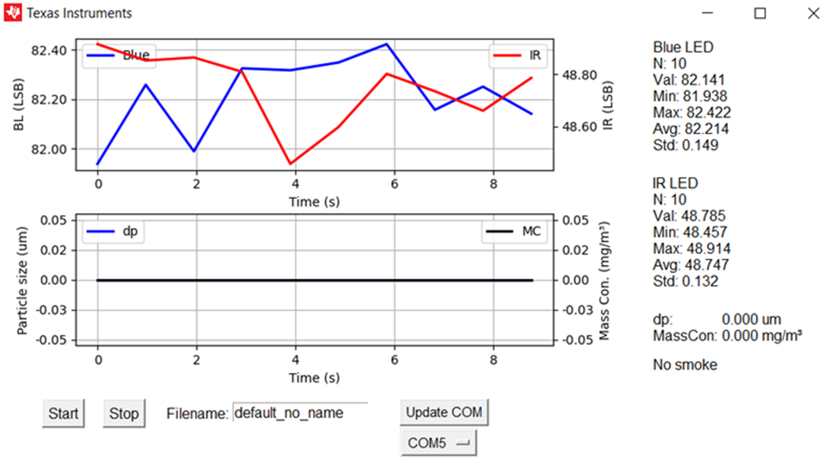
A GUI developed with Python is included with this reference design. Figure 3-8 shows a screen capture of the GUI. In addition to the graphical view, the data that is displayed is also presented live in a terminal window as shown in Figure 3-9.
 Figure 3-8 GUI Screen Capture
 Figure 3-9 GUI Terminal Window
Output
Figure 3-9 GUI Terminal Window
OutputTo use the smoke detector GUI:
- The smoke detector GUI is distributed via Python
source code, and must be built into an executable before use. Unzip the file
containing the Python source code, and refer to the accompanying
READMEfor instructions on building the GUI. - Connect the SASI sensing board to the LaunchPad Development Kit. Only the integrated XDS110 emulator on the LaunchPad is needed for PC communication. The rest of the LaunchPad is not activated.
- Connect the LaunchPad to the PC via USB cable.
- Open the GUI
sasi_smoke_detector_m0l1306.exe.- Make sure to start with clean air.
- Wait for 12 seconds after first time power up or reset for proper calculation of base signal.
- Click the Update COM button for COM port auto-detection.
- Enter the filename for data logging.
- The log file is stored in
the
capture\<date>\folderalong with an image of the GUI plot. - Multiple logs are appended with “_0”, “_1”, and so forth.
- Each file logs 1000 entries, and a new file is generated every 1000 entries.
- The log file is stored in
the
- Set the smoke trigger threshold value in the Least Significant Bit (LSB).
- Click the Start button to start
measurement.
- Measurement statistics are displayed on the side in LSB.
- Smoke indication (no smoke or smoke detected) is also displayed based on whether the signal exceeds the threshold.
- Estimated particle size and mass concentration are also displayed.
- Click the Stop button to stop
measurement.
- Data is automatically logged. Time and signal response in LSB from the IR and Blue LEDs, particle size estimation, and the smoke detection flag are also streamed to the terminal.