TIDUF52 December 2023 MSPM0L1303 , MSPM0L1304 , MSPM0L1305 , MSPM0L1306 , MSPM0L1343 , MSPM0L1344 , MSPM0L1345 , MSPM0L1346
- 1
- Description
- Resources
- Features
- Applications
- 6
- 1System Description
- 2System Overview
- 3Hardware, Software, Testing Requirements, and Test Results
- 4Design and Documentation Support
- 5About the Author
3.4.2 Ambient Light Testing Results
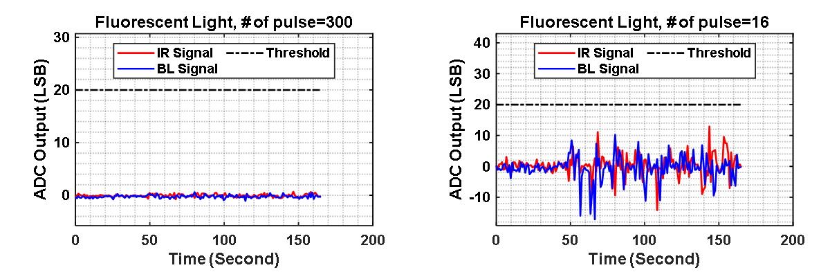
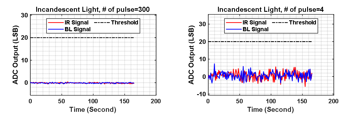
Figure 3-14 and Figure 3-15 show the transient response of the smoke detection module for fluorescent and incandescent light conditions with different number of pulses, respectively. For the fluorescent light scenario, the noise performance shows no degradation with 300 pulses. Reducing the number of pulses to 16, larger variations are seen in the panel on the right side of Figure 3-14. This is due to the fact that fluorescent light has interference tones at 44 kHz and the harmonics of the 44 kHz fundamental in the power spectrum, which is close to the modulation frequency. Even though with large variation, the smoke detection module does not trigger a false alarm with a typical threshold of 20 LSB.
Incandescent light interference (main tone at 120 Hz); however, is strongly rejected (> 60 dB) by the bandpass filter in the modulation signal chain. The tests show no significant change of noise performance with the light on and off, even with a 4-pulse scenario.
 Figure 3-14 Transient Response Output With
Fluorescent Light Interference
 Figure 3-15 Transient Response Output With
Incandescent Light Interference