TIDUF52 December   2023 MSPM0L1303 , MSPM0L1304 , MSPM0L1305 , MSPM0L1306 , MSPM0L1343 , MSPM0L1344 , MSPM0L1345 , MSPM0L1346


  1.   1
  2.   Description
  3.   Resources
  4.   Features
  5.   Applications
  6.   6
  7. 1System Description
    1. 1.1 Key System Specifications
  8. 2System Overview
    1. 2.1 Block Diagram
    2. 2.2 Design Considerations
      1. 2.2.1 Photoelectric Smoke Detector Background – DC-Based Signal Chain
      2. 2.2.2 Modulation-Based Smoke Detection Signal Chain
      3. 2.2.3 Optical Sensing AFE Design
        1. 2.2.3.1 TIA
        2. 2.2.3.2 BPF
        3. 2.2.3.3 Demodulator and Integrator
        4. 2.2.3.4 LED Driver
      4. 2.2.4 Optical and Mechanical Design
    3. 2.3 Highlighted Products
      1. 2.3.1 MSPM0L1306
      2. 2.3.2 TLV9062S
      3. 2.3.3 TPS7A24
      4. 2.3.4 TS5A623157
      5. 2.3.5 SN74LVC1G66
      6. 2.3.6 HDC2010
  9. 3Hardware, Software, Testing Requirements, and Test Results
    1. 3.1 Hardware Requirements
      1. 3.1.1 Power
      2. 3.1.2 Communication Interface
      3. 3.1.3 Headers
    2. 3.2 Software Requirements
      1. 3.2.1 Getting Started Firmware
      2. 3.2.2 Measurements and Smoke Detection
      3. 3.2.3 Additional Demonstration Functionality
      4. 3.2.4 Smoke Detector GUI
    3. 3.3 Test Setup
      1. 3.3.1 UL217 Smoke Box and Fire Testing Setup
      2. 3.3.2 Ambient Light Testing Setup
      3. 3.3.3 Air-Quality Sensing Test Setup
    4. 3.4 Test Results
      1. 3.4.1 UL217 Testing Results
      2. 3.4.2 Ambient Light Testing Results
      3. 3.4.3 Air-Quality Sensing Test Results
      4. 3.4.4 Power Testing Results
      5. 3.4.5 Fire Room Smoke Testing
  10. 4Design and Documentation Support
    1. 4.1 Design Files
      1. 4.1.1 Schematics
      2. 4.1.2 BOM
      3. 4.1.3 CAD Files
    2. 4.2 Tools and Software
    3. 4.3 Documentation Support
    4. 4.4 Support Resources
    5. 4.5 Trademarks
  11. 5About the Author

Ambient Light Testing Setup

To evaluate the smoke detection module performance under ambient light, the module samples are tested with testing facility and method subjected to the light stability testing in UL217 (See section 47.1f of the UL217 9th edition). The test setup is shown in Figure 3-12 and results are presented in Section 3.4.2.
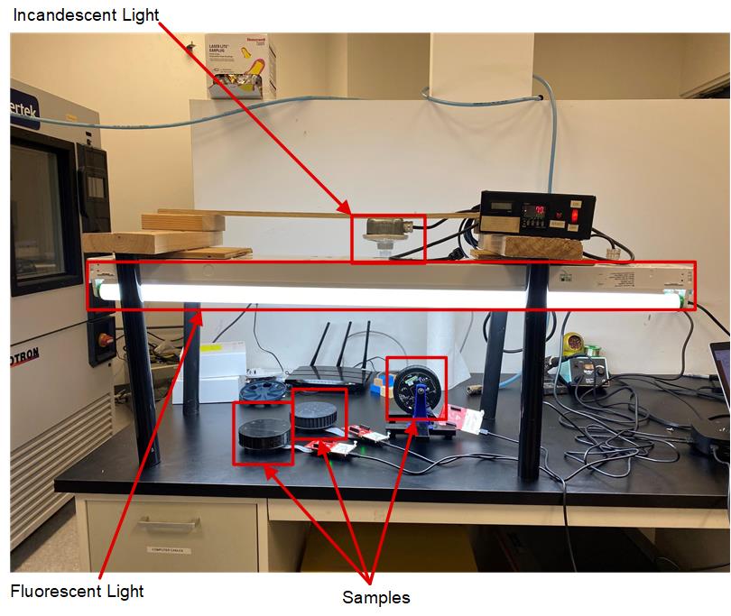
GUID-20231020-SS0I-MSQK-BGDB-HKN51PQCXQN4-low.jpg Figure 3-12 Testing Setup of Ambient Light Effects on Smoke Detection Module