TIDUF52 December 2023 MSPM0L1303 , MSPM0L1304 , MSPM0L1305 , MSPM0L1306 , MSPM0L1343 , MSPM0L1344 , MSPM0L1345 , MSPM0L1346
- 1
- Description
- Resources
- Features
- Applications
- 6
- 1System Description
- 2System Overview
- 3Hardware, Software, Testing Requirements, and Test Results
- 4Design and Documentation Support
- 5About the Author
2.2.4 Optical and Mechanical Design
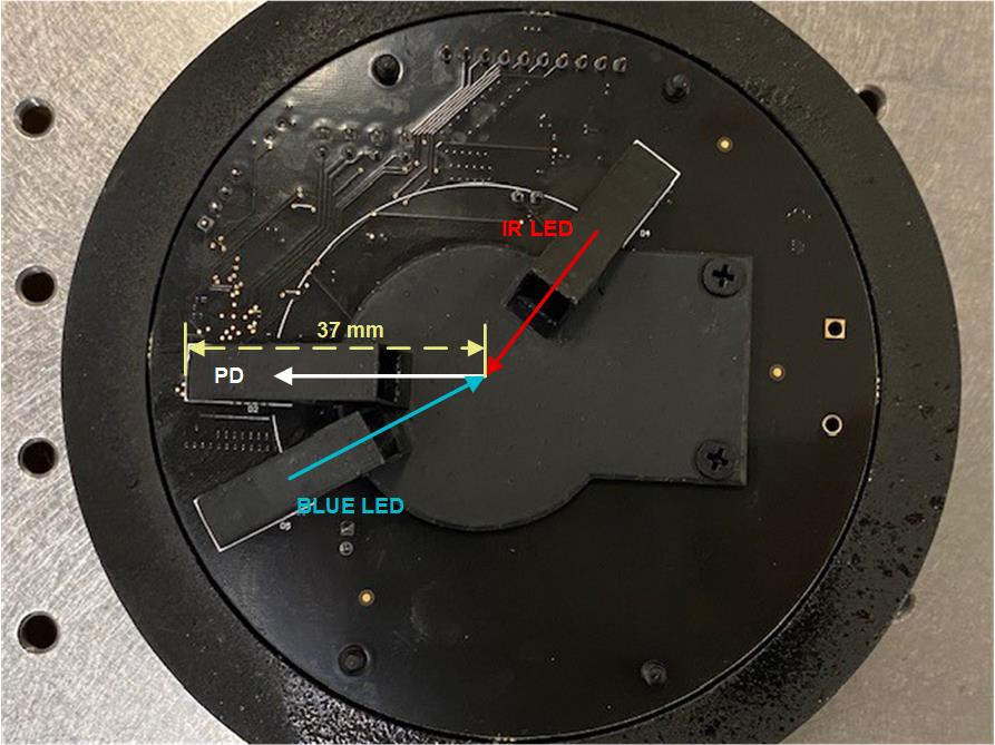
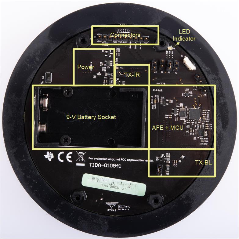
This section covers the customized optical front end and mechanical design. A 2-LED (1 BLUE + 1 IR) and 1-PD design is adopted to enable the smoke type analysis and reduce the false alarm of the smoke detection due to nuisance sources. Figure 2-12 shows a top-down view of the module board to illustrate the arrangement of the optical elements. The angle between the IR LED (TSAL6100) and the PD (SFH213) is forward 125 degrees. The angle between the BLUE LED (C503B-BAN) and the PD is backward 30 degrees, which is specifically designed to leverage both BLUE and IR sensing data to perform analysis of the smoke type. The through-hole optical parts are first inserted into a customized 3D-printed container and soldered onto the top side of the sensing board. The bottom side of the sensing board contains a 9-V battery socket, sensing electronics, LED indicator for smoke alarm, and connectors for communication. Figure 2-13 shows the picture of the top-down view of the bottom side of the board.
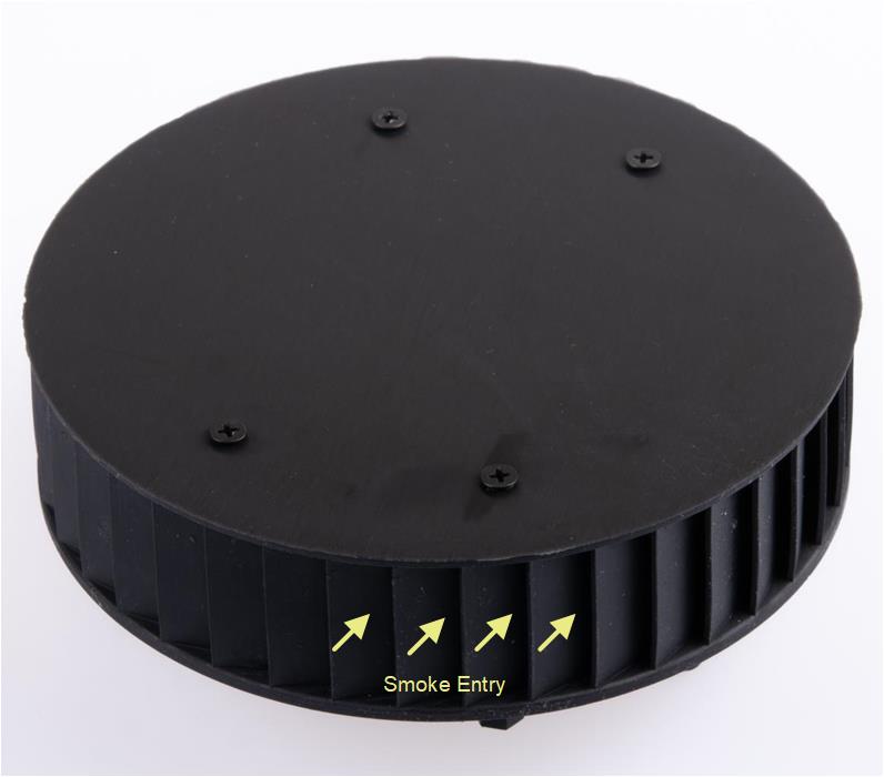
A 3D-printed top cover is attached to the top-side of the board (the same side of the optical front end) to block environmental interference such as insects and ambient light, providing a tractable smoke sensing environment. To obtain the best optical performance, the printed cover is spray-painted with matte black paint to reduce the stray-light reflection from the cover. Figure 2-14 shows the complete view of the smoke detector module with cover. Download the 3D step files of these mechanical designs from the TIDA-010941 tool folder.
 Figure 2-12 Top-Down View of the Optical Front End With Sensing Board
 Figure 2-13 Top-Down View of the Bottom-Side Sensing Board
 Figure 2-14 Complete View of Smoke Detector Module