TIDUF52 December 2023 MSPM0L1303 , MSPM0L1304 , MSPM0L1305 , MSPM0L1306 , MSPM0L1343 , MSPM0L1344 , MSPM0L1345 , MSPM0L1346
- 1
- Description
- Resources
- Features
- Applications
- 6
- 1System Description
- 2System Overview
- 3Hardware, Software, Testing Requirements, and Test Results
- 4Design and Documentation Support
- 5About the Author
3.2.1 Getting Started Firmware
The firmware for this reference design is released as Demonstration application examples and are available in the latest MSPM0 SDK. An optional Python® graphical user interface (GUI) allows developers to adjust the Blue and IR LED threshold values and observe the system response. The GUI is available at TIDA-010941.
The demonstration application examples can be evaluated online using the cloud version of CCS Theia, known as CCS Cloud IDE, or offline using the desktop versions of CCS Theia or CCS Eclipse, a legacy IDE.
The cloud version of CCS Theia is referred to as CCS Cloud IDE or CCS Cloud throughout the document.
To evaluate the demonstration application examples online using CCS Cloud, follow the steps below:
- Open the MSPM0 SDK in TI Developer Zone.
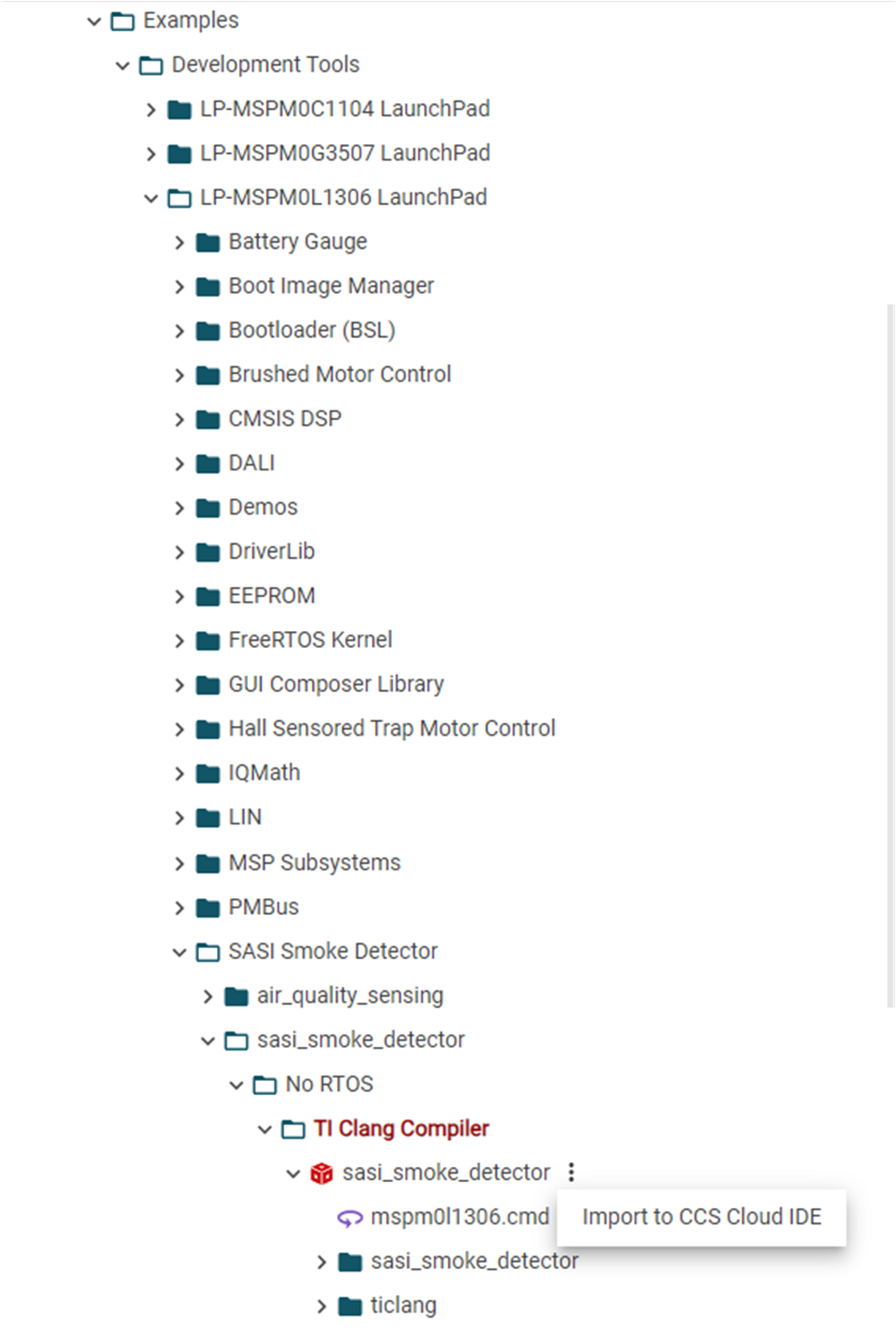
- Navigate to the SASI Smoke Detector
examples directory by clicking Examples->Development
Tools->LP-MSPM0L1306->SASI Smoke Detector. Click the 3 dots at the right
side of the example, and click Import to CCS Cloud IDE.
 Figure 3-3 Firmware Demonstration
Example SDK Directory Path
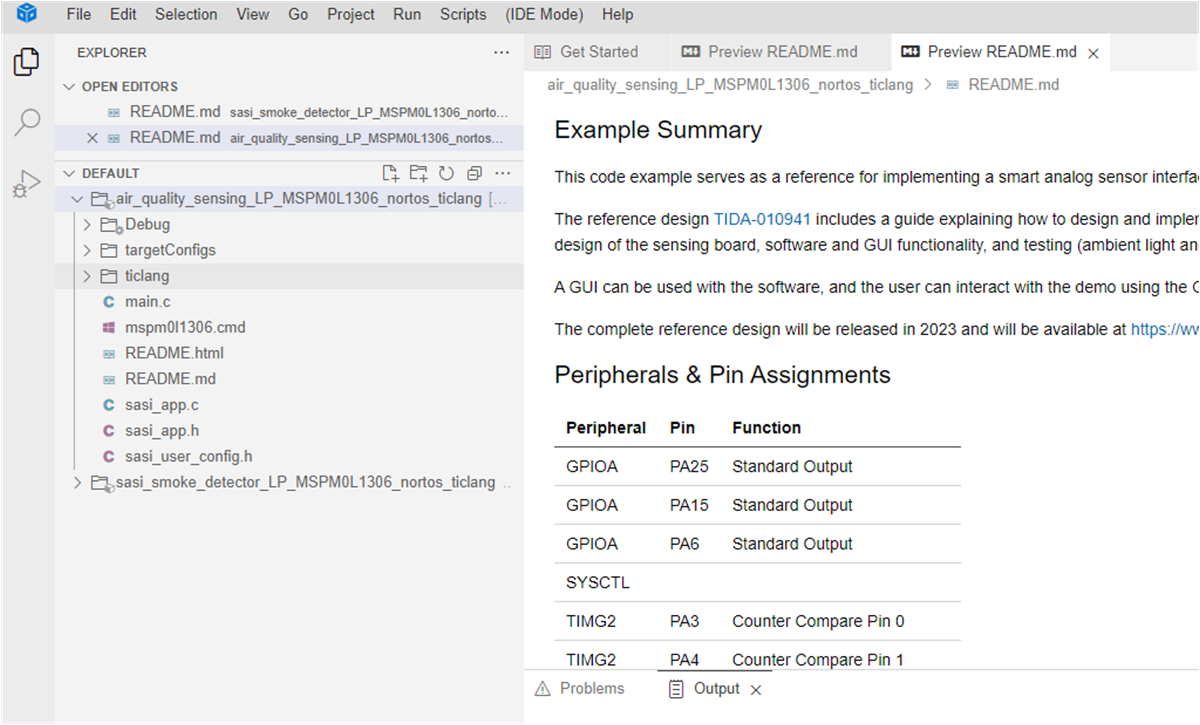
 - After importing the examples to the CCS Cloud
IDE, the project explorer window appears as follows:
 Figure 3-4 CCS Cloud IDE After
Firmware Demonstration Example Import
 - The imported examples can be built and loaded onto the device as normal. See the Code Composer Studio Theia User’s Guide for more details and instructions on using the cloud and desktop versions of CCS Theia.
To evaluate the demonstration application examples offline using the desktop versions of CCS Theia or CCS Eclipse, see the MSPM0 SDK QuickStart Guide for CCS and the MSPM0 SDK QuickStart Guide for CCS Theia for import instructions into those tools.
Developers can use these code examples as references for implementing a smoke detector or air-quality sensing system using the Smart Analog Sensor Interface (SASI) sensing board.