TIDUF52 December 2023 MSPM0L1303 , MSPM0L1304 , MSPM0L1305 , MSPM0L1306 , MSPM0L1343 , MSPM0L1344 , MSPM0L1345 , MSPM0L1346
- 1
- Description
- Resources
- Features
- Applications
- 6
- 1System Description
- 2System Overview
- 3Hardware, Software, Testing Requirements, and Test Results
- 4Design and Documentation Support
- 5About the Author
3.4.3 Air-Quality Sensing Test Results
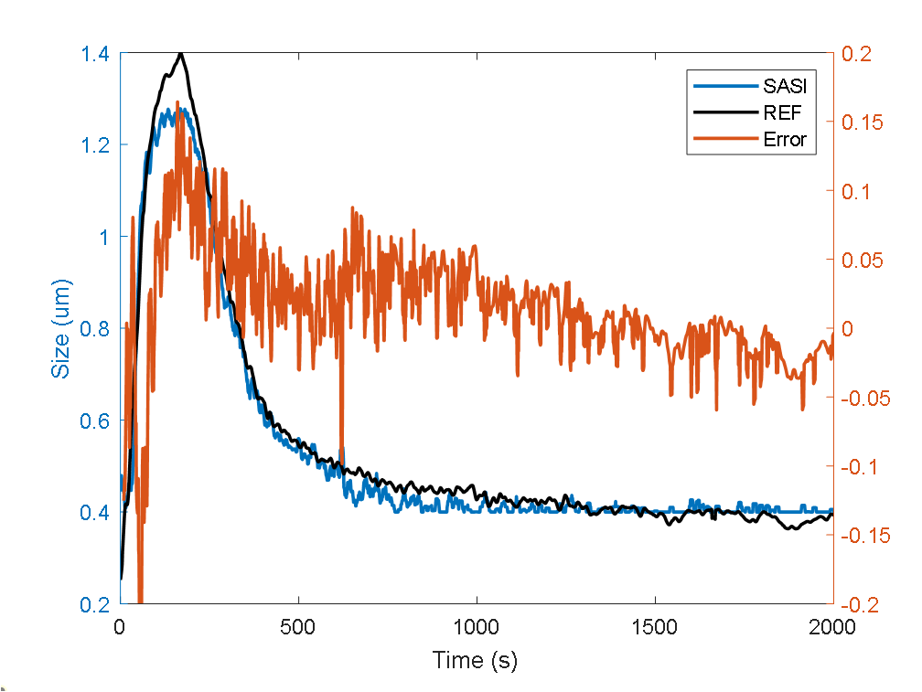
This section shows the air-quality test results of the smoke sensing module with respect to the reference. Figure 3-16 shows the real-time averaged particle size reading of the smoke sensing module along with the reference. Within the averaged particle size range of 0.4 µm to 1.4 µm, the smoke sensing module shows a ±0.1-µm accuracy with respect to the laser-based reference.
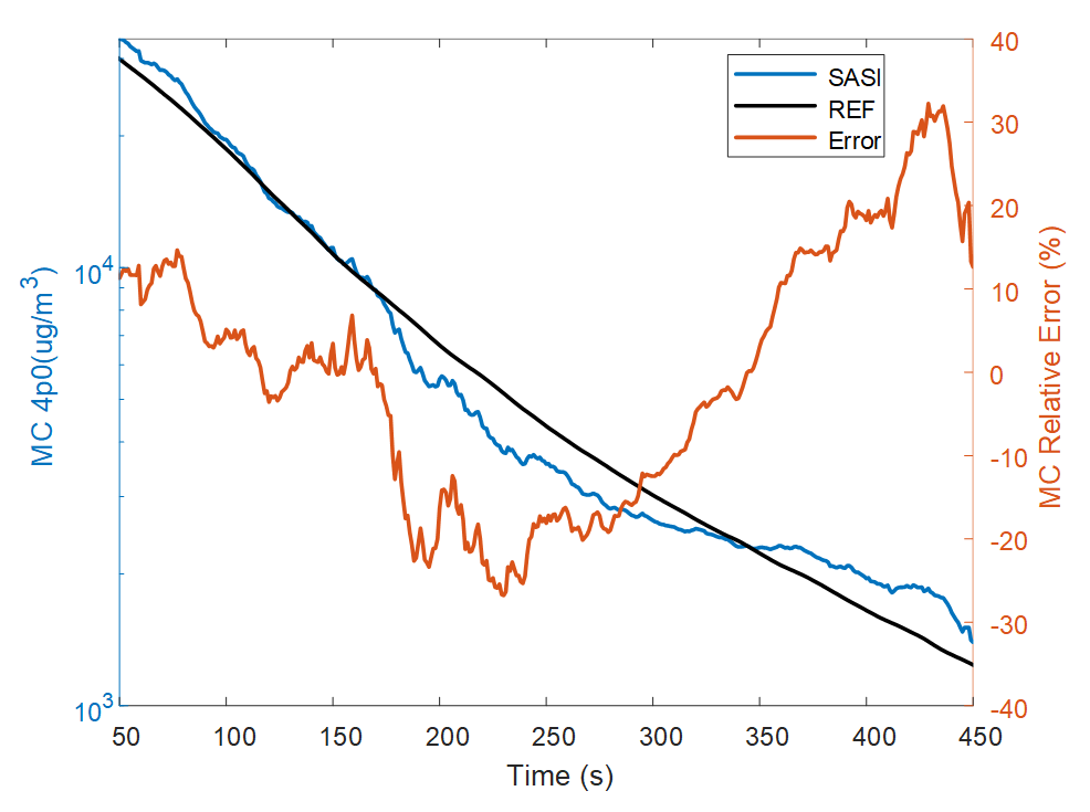
Figure 3-17 shows the real-time mass concentration (PM4) reading comparison of the smoke sensing module and the reference (y-axis MC 4p0 = Mass Concentration PM4). From the 2000 µg/m3 to 30000 µg/m3 measurement range, the smoke sensing module can achieve ±30% relative measurement accuracy with respect to the reference. Some of this error can be attributed to the difference in placement of the smoke-sensing module and the reference in a chamber that is not exactly uniform. It is estimated that the real error level achievable is approximately ±20%. Note that the lower bound measurement error is mainly limited to the quantization noise of the system. Enabling a higher signal chain gain, this limitation can be reduced.
 Figure 3-16 Real-Time Averaged Particle
Size Measurement Comparison
 Figure 3-17 Real-Time Mass Concentration
Measurement Comparison