TIDUF82A August 2024 – November 2024 DRV8162 , INA241A , ISOM8710
- 1
- Description
- Resources
- Features
- Applications
- 6
- 1System Description
-
2System Overview
- 2.1 Block Diagram
- 2.2 Design Considerations
- 2.3 Highlighted Products
- 3Hardware, Software Test Requirements and Test Results
- 4Design and Documentation Support
- 5About the Authors
- 6Revision History
3.3.4 Phase-Current Measurements
This section shows the phase-current measurement performance generating an open loop rotating field for the motor control.
 Figure 3-26 TIDA-010956 Diagram of the Test Setup for the Current Measurements
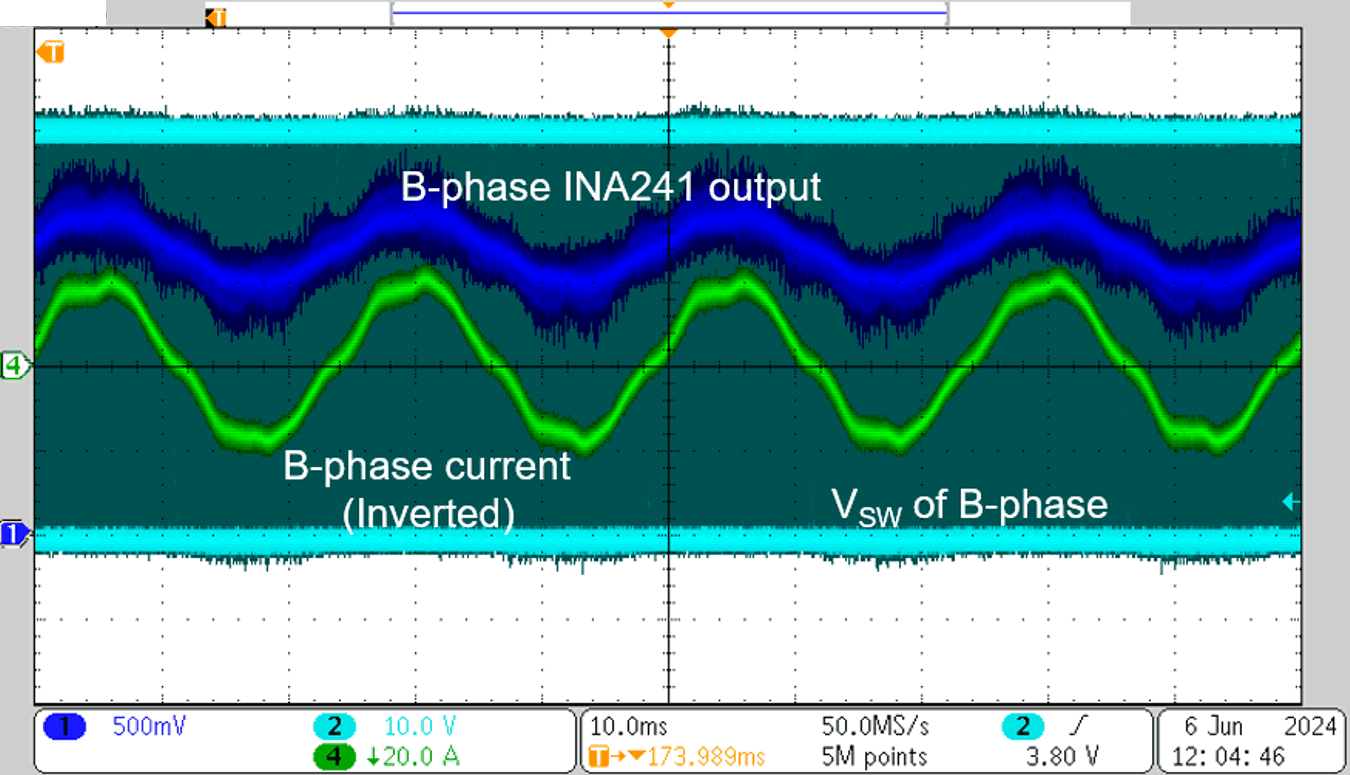
Figure 3-27 shows the motor current (CH4 in green) and the current-sense amplifier output voltage (CH1 in deep blue) of the INA241 measurements in B-phase. The switching node voltage is also shown (CH2 in light blue).
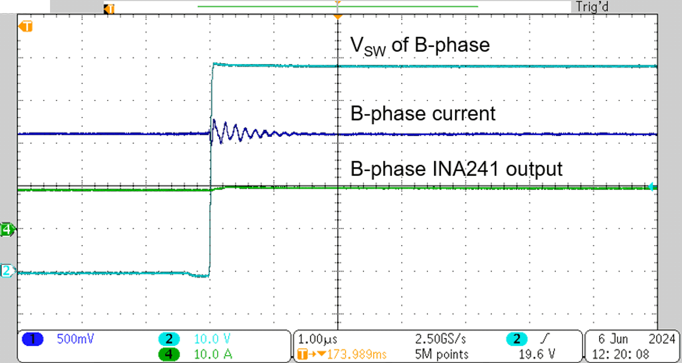
Figure 3-28 shows the sinusoidal-like waveform output of the INA241. Obvious distortions of the sine wave are displayed as the system is running in open loop. Figure 3-28 shows the common-mode performance of the INA241.
 Figure 3-27 Rotating Current Measured on the INA241 Output
 Figure 3-28 INA241 Output Measured During Switch Point
This measurement captures the worst-case scenario of the settling time of the amplifier. Observe that a maximum settling time of around 1.0μs can be expected.