-
When to Replace a Relay With a Multiplexer
- 1
- Abstract
- Trademarks
- 1 Size Requirement
- 2 Reliability Over Time
- 3 Power Consumption
- 4 Switching Speed and Hot Switching
- 5 Signal Isolation
- 6 Capacitance
- 7 On-Resistance and Flatness
- 8 Leakage Current
- 9 Integrated Protection
- 10Latch-up Immunity
- 11Galvanic Isolation
- 12Conclusion
- 13References
- 14Revision History
- IMPORTANT NOTICE
When to Replace a Relay With a Multiplexer
Abstract
As many systems such as automated test and measurement and factory automation become smaller and more cost constrained, one potential for savings can come from shrinking the signal chain. Almost every system contains some type of switching and historically, mechanical relays were used. This implementation can be good from a performance perspective, but comes with a significant tradeoff on size, cost, and reliability. In more modern designs, Photorelays are often used instead of mechanical relays. These typically take a small hit on signal performance to drastically reduce size and cost while increasing reliability. Many systems can be further optimized by using TI's integrated Flat On-Resistance Multiplexers instead of Photorelays. In this application note, we go over the differences in performance, cost, size, and reliability between these three solutions.
Though these three devices can serve similar purposes, their internal designs are very different. Mechanical relays typically consist of an inductive coil and a physical switch. When current excites the coil, it becomes magnetic and pulls two pieces of metal together. Photorelays have a similar operation except instead of a coil, an LED is used to drive the gate of a MOSFET on/off. A multiplexer integrates multiple drivers and MOSFETs onto the same chip and drives the gate with a constant voltage source. As a result, Multiplexers save PCB space compared to Photorelay and mechanical relays.
 Figure 1-1 Equivalent Circuits (from
left to right): Mechanical Relay, Photorelay, Multiplexer
 Trademarks
All trademarks are the property of their respective owners.
1 Size Requirement
One of the largest benefits to an integrated multiplexer switching design is size. For example, in a 16-channel system, 16 SPST (1:1) mechanical relays would be needed, accounting for >450mm2 board area. This is before including any relay driver ICs. Compare this to a Photorelay design and the user can see that the size requirements reduce dramatically. But Photorelays can not be driven directly through GPIO and need an LED driver to control the state of each switch. This adds to the design size and increases the system complexity, as well as power requirements. TI’s Multiplexer design such as the TMUX821x and TMUX7612 do not require any additional ICs. Each individual switch can be controlled by standard digital pins with 1.8V Logic. As a result, TI’s switch design is even smaller than a comparable Photorelay design.
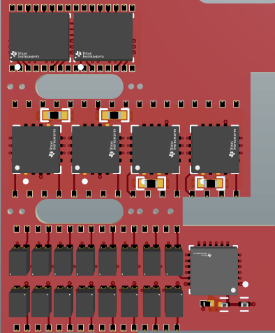
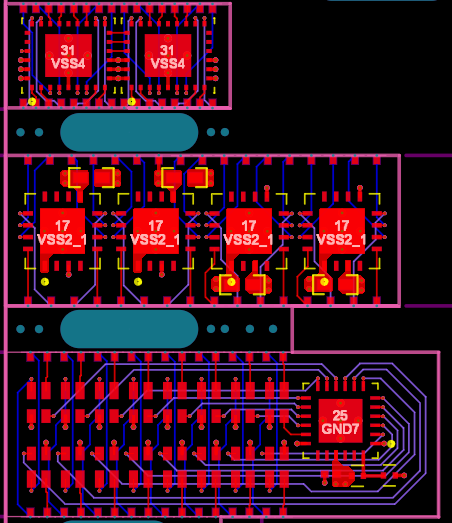
 Figure 1-1 16 Channel, 50V design
Size Comparison (drawn to scale)
  Figure 1-2 TMUXS7614D top,
TMUX7612/TMUX8212 middle, Photorelay Bottom
 As design size becomes a larger concern, routing and layout become a major consideration. The table below compares the actual design size of these three options with routing. You can see while the package density of the TMUX7612 and Photorelay are similar, when routing and layout is considered the space savings is more significant. And the TMUXS7614D saves significantly more area on top of this by integrating the passive components and optimizing the pinout.
TMUXS7614D |
TMUX7612 TMUX8212 |
Photorelay | |
|---|---|---|---|
| Total Package Area | 2.5mm2/ch | 4.0mm2/ch | 4.2mm2/ch |
| Total PCB Area | 3.18mm2/ch | 9.13mm2/ch | 11.22mm2/ch |
| Area Savings | 129mm2 (70% reduction) | 33.5mm2 (20% reduction) | - |
1.1 Optimized Layout and Control
Another option you have with integrated multiplexers or switches is optimized layout and control. Most analog switches are GPIO CMOS input control which already has advantages over LED input controls like photorelays. But this can be further be optimized with SPI controlled devices like the TMUXS7614D. As seen in the previous example, if you are trying to control a 16 channel system, you normally need 16 GPIO controls or 16 LED drive channels for an analog switch and photorelay respectively. With a SPI controlled multiplexer, the control can be connected in daisy chain, meaning you only need 3 control lines (clock, data, chip select) to control all 16 channels independently. And this can be scaled up to any channel count, with only 3 control pins.
Additionally, the TMUXS7614D integrates the decoupling capacitors and has an optimized layout so the routing and placement can be done with minimal empty space around the switch. This enables a much higher effective channel density when routing is considered.