-
Optimal Implementation of 25G/28G Retimers versus Redrivers in Common Applications SNLA335B september 2019 – may 2023 DS250DF210 , DS250DF230 , DS250DF410 , DS250DF810 , DS280BR810 , DS280BR820 , DS280DF810 , DS280MB810
-
Optimal Implementation of 25G/28G Retimers versus Redrivers in Common Applications
- Optimal Implementation of 25G/28G Retimers versus Redrivers in Common Applications
- Trademarks
- 1Overview of TI 25G/28G Retimers and Redrivers
- 2When to use a Retimer Versus Redriver
- 3Retimers for Common Network Interfaces
- 4Link Training Support With TI Signal Conditioning Devices
- 5Retimer and Redrivers Part Selection
- 6Revision History
- IMPORTANT NOTICE
Optimal Implementation of 25G/28G Retimers versus Redrivers in Common Applications
Optimal Implementation of 25G/28G Retimers versus Redrivers in Common Applications
This document provides application-based criteria to assist system developers in selecting between 25G/28G retimers and redrivers. Functional background and description of relevant performance parameters and features for these devices are included to facilitate part number comparison and selection. Channel insertion loss, networking standard compliance needs and link training support are all reviewed in the context of component selection of retimers versus redrivers to achieve signal conditioning and link reach extension.
Trademarks
All trademarks are the property of their respective owners.
1 Overview of TI 25G/28G Retimers and Redrivers
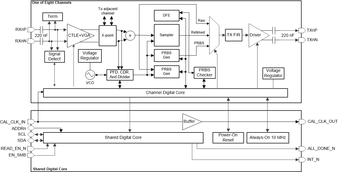
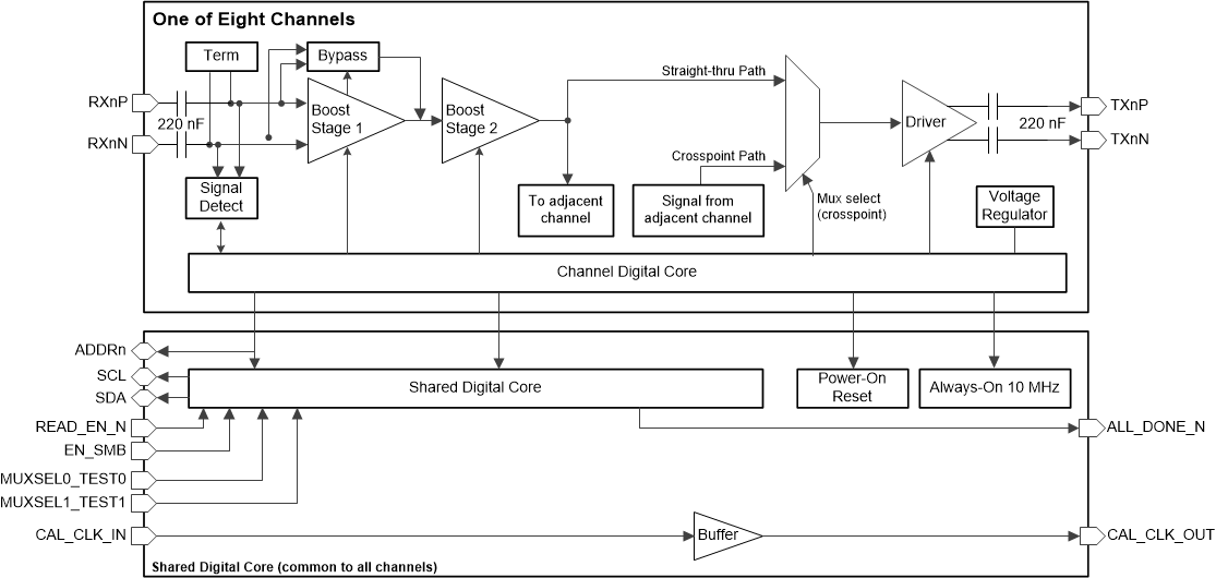
Figure 1-1 and Figure 1-2 illustrate the functional block diagrams for TI's 25G/28G retimers and redrivers. As evident from the block diagrams, the retimer and redriver have a few key functional differences.
- The retimer implements clock and data recovery (CDR) and sampler functional blocks, thus enabling it to output a retimed version of the input signal with lower jitter. The redriver on the other hand does not incorporate the retiming-CDR related functional blocks.
- The redriver implements a two-stage continuous time linear equalizer (CTLE) as its only form of receive equalization.
- In addition to CTLE, the retimer also implements a decision feedback equalizer (DFE). Thus the retimer is equipped with more enhanced post-cursor equalization function.
- The retimer incorporates additional diagnostic functions not available on the redriver, including PRBS pattern generation and checking and eye monitor functions.
 Figure 1-1 DS280DF810 Retimer Functional Block Diagram
 Figure 1-2 DS280MB810 Redriver Functional Block Diagram
2 When to use a Retimer Versus Redriver
Table 2-1 lists a high-level summary of chip-to-chip interface types based on their transmission channel's insertion loss at around the Nyquist frequency for 25Gbps data rate. The amount of channel loss will dictate the level of signal conditioning required for an error free chip-to-chip link. Some portion of system interconnects will have channel loss that is within the equalization compensation capability of the chips being linked together. Such links do not require signal conditioning. Links requiring a moderate amount of compensation (up to 20dB) may use a redriver instead of a retimer, in that way realizing some relative savings in power consumption and cost. Links involving transmission across a channel with very high loss require the use of a retimer.
| 25Gbps CHIP-TO-CHIP LINK CASE | RECOMMENDED SIGNAL CONDITIONING (SigCon) LEVEL |
|---|---|
| Channel loss within the chip's compensation capability | No SigCon required |
| Channel loss exceeding chip compensation by up to 20dB | TI 25G/28G redriver |
| 20dB < channel loss < 35dB | TI 25G/28G retimer |