-
New LED Drivers Enhance Your Automotive Lighting Solutions
New LED Drivers Enhance Your Automotive Lighting Solutions
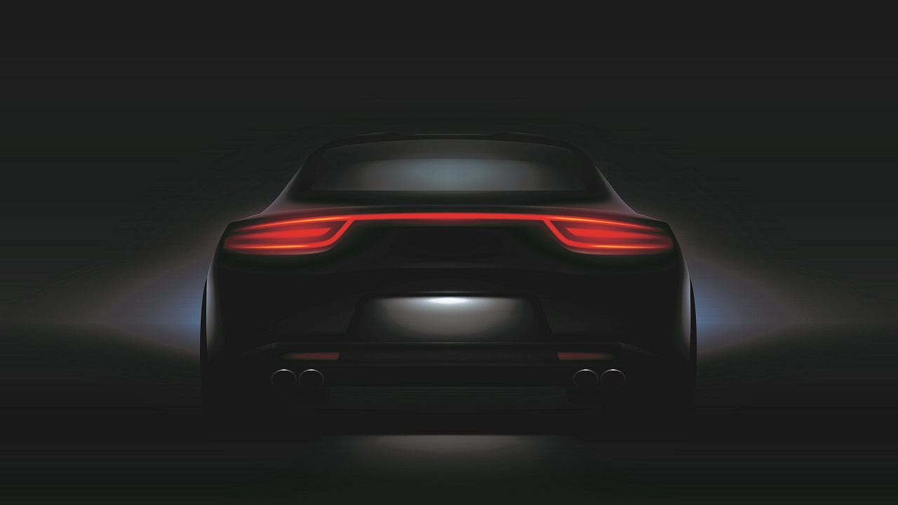
Automotive rear lighting systems have evolved from a signal that simply indicates a braking automobile to a symbol of an automotive brand.
Automotive rear lighting systems need to accommodate custom designs from automakers while still remaining useful for signaling. In this article, I’ll look further into automotive rear lighting system trends, new challenges that these trends bring and solutions that address these challenges.
The first trend is unique animation in automotive rear lamps to symbolize a brand identity. Increased demand for complex animation in automotive lighting requires independent control of LEDs, but the first design challenge is that you cannot use enough analog LED drivers to drive the number of LEDs required to independently control a lighting application. Only LED drivers with a digital interface can effectively drive pixel-controlled lighting applications. Figure 1-1 shows the architectures for pixel control of a traditional rear lamp and a new rear lamp.
 Figure 1-1 Traditional and new rear lamp
architectures for pixel control
Figure 1-1 Traditional and new rear lamp
architectures for pixel controlThe second market trend of automotive rear lighting systems is that the shape of an automotive rear lamp is getting longer – sometimes, as shown in Figure 1-2, the rear lamp extends across the entire rear end of the car body.
 Figure 1-2 Long automotive rear
lamp
Figure 1-2 Long automotive rear
lampAutomotive rear lamps that extend across the back of an automobile mean long wires across the entire printed circuit board. This presents a significant design issue, because the LED drivers must connect directly to a microcontroller (MCU), with wires in traditional single-ended interfaces for long-distance off-board communication. It is difficult for such a complex architecture to meet strict electromagnetic compatibility (EMC) requirements. Therefore, using an external physical layer transceiver is essential to effectively implement long distance off-board communication for automotive lighting, as shown in Figure 1-3.
 Figure 1-3 Typical application diagram
for long-distance off-board communication
Figure 1-3 Typical application diagram
for long-distance off-board communicationA third market trend is increasing the importance of robustness. The robustness of automotive rear lamps is directly connected to road safety, so drivers need to check the rear lamps of their automobiles regularly. Even a tiny mistake can lead to an accident. That’s why it’s essential to have automotive rear lighting systems capable of conducting self-diagnostics.
TI’s TPS929120-Q1 helps designers resolve the design challenges arising from automotive market trends. The TPS929120-Q1 is an automotive 12-channel LED driver with FlexWire interface that address the increasing need to individually control each LED.
By using an industry-standard CAN physical layer, the Universal Asychronous Receiver Transmitter-based FlexWire interface of the TPS929120-Q1 easily accomplishes long-distance off-board communication without impacting EMC.
Furthermore, the TPS929120-Q1 meets multiple regulation requirements with open-circuit, short-to-ground and single LED short-circuit diagnostics. A configurable watchdog automatically sets fail-safe states when the MCU connection is lost, and with programmable electrically eraseable programmable read-only memory, you can set the TPS929120-Q1 for different application scenarios.
The TPS929120-Q1 enables unique automotive lighting designs with improved performance as well.
Additional resource:
- Read the white paper, “Trends and topologies for automotive rear lighting systems.”
IMPORTANT NOTICE AND DISCLAIMER
TI PROVIDES TECHNICAL AND RELIABILITY DATA (INCLUDING DATASHEETS), DESIGN RESOURCES (INCLUDING REFERENCE DESIGNS), APPLICATION OR OTHER DESIGN ADVICE, WEB TOOLS, SAFETY INFORMATION, AND OTHER RESOURCES “AS IS” AND WITH ALL FAULTS, AND DISCLAIMS ALL WARRANTIES, EXPRESS AND IMPLIED, INCLUDING WITHOUT LIMITATION ANY IMPLIED WARRANTIES OF MERCHANTABILITY, FITNESS FOR A PARTICULAR PURPOSE OR NON-INFRINGEMENT OF THIRD PARTY INTELLECTUAL PROPERTY RIGHTS.
These resources are intended for skilled developers designing with TI products. You are solely responsible for (1) selecting the appropriate TI products for your application, (2) designing, validating and testing your application, and (3) ensuring your application meets applicable standards, and any other safety, security, or other requirements. These resources are subject to change without notice. TI grants you permission to use these resources only for development of an application that uses the TI products described in the resource. Other reproduction and display of these resources is prohibited. No license is granted to any other TI intellectual property right or to any third party intellectual property right. TI disclaims responsibility for, and you will fully indemnify TI and its representatives against, any claims, damages, costs, losses, and liabilities arising out of your use of these resources.
TI’s products are provided subject to TI’s Terms of Sale (www.ti.com/legal/termsofsale.html) or other applicable terms available either on ti.com or provided in conjunction with such TI products. TI’s provision of these resources does not expand or otherwise alter TI’s applicable warranties or warranty disclaimers for TI products.
Mailing Address: Texas Instruments, Post Office Box 655303, Dallas, Texas 75265
Copyright © 2023, Texas Instruments Incorporated