-
Can Your RS-485 Communication Survive the Great Outdoors?
Can Your RS-485 Communication Survive the Great Outdoors?
Kaitlyn Mazzarella
RS-485 transceivers are designed to withstand harsh environments. In addition to noisy factory environments, this means RS-485 transceivers must also be robust enough to operate outdoors, where communication can be affected by voltage surge events, such as lightning strikes.
So, how do you know if your RS-485 communication is capable of surviving a high-voltage event?
The International Electrotechnical Commission has established the IEC 61000-4-5 surge standard to help engineers determine the level of surge protection of a system. The IEC 61000-4-5 standard is critical for applications with outdoor communication, such as remote radio units, air conditioning units and Internet Protocol (IP) surveillance cameras.
Understanding this standard is essential to ensuring that your systems can withstand anything nature may throw your way. This article will focus on different ways to protect your system from outdoor surge elements while showing you how to optimize your design to save space and reduce components.
| Integrated surge protection with a smaller footprint | |

|
Introducing the THVD1429, a 3.3-V to 5-V RS-485 transceiver with integrated surge protection. Learn how it helps increase system protection while reducing bill of materials in RS-485 designs in the video, Integrated surge protection for RS-485 communications. |
What Is the IEC 61000-4-5 Surge Immunity Standard?
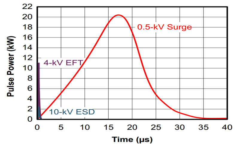
The IEC 61000-4-5 surge standard is one of the most demanding tests performed on an RS-485 transceiver; the test models a lightning strike or industrial surge. Figure 1 compares three of the commonly required tests for RS-485. The 0.5-kV surge (the red trace) is magnitudes longer in duration and higher in energy (due to low source impedance) than the 4-kV electrical fast transient (EFT) (the purple trace) and 10-kV electrostatic discharge (ESD) (blue trace) tests.
 Figure 1 A Surge Test Compared to EFT
and ESD Tests
Figure 1 A Surge Test Compared to EFT
and ESD TestsSurge is a common and mandatory requirement for systems exposed to outdoor elements. IEC surge tests simulate the inrush of current into a transceiver, and there are different levels of IEC standard classification criteria (outlined in Table 1). System-level designs commonly have to meet Class 2 (a 1-kV test) or Class 3 (a 2-kV test).
| Class | Test level | Maximum peak current (at 2 Ω) |
|---|---|---|
| 0 | 25 V | 12.5 A |
| 1 | 500 V | 250 A |
| 2 | 1 kV | 500 A |
| 3 | 2 kV | 1,000 A |
| 4 | 4 kV | 2,000 A |
There are two ways to protect against surge events: (1) with a more complex discrete solution using an RS-485 transceiver and several external protection components, or (2) with a surge-integrated RS-485 transceiver. Let’s first take a look at what the discrete approach requires, and then we can take a look at how TI’s latest RS-485 transceivers, the THVD1429 (and lower-speed-option THVD1419), can help simplify the solution.
A Discrete Surge Implementation
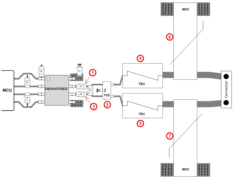
Protection devices such as transient voltage suppression (TVS) diodes, metal-oxide varistors (MOVs) and gas discharge tubes are often implemented externally to the transceiver in order to limit the voltage and absorb the surge current. Figure 2 shows the IEC ESD, EFT and Surge Protected RS-485 Reference Design with a standard SN65HVD3082E RS-485 transceiver and the additional external components required to provide surge protection.
 Figure 2 Discrete Solution with up to
Seven Additional Components to Surge-protect an RS-485 Transceiver
Figure 2 Discrete Solution with up to
Seven Additional Components to Surge-protect an RS-485 TransceiverThe first challenge with this approach is that it requires designing with additional components. The second challenge is that very few of these protection devices can comply with the surge standard - meaning that component selection can become very challenging and expensive.
The setup in Figure 2 can achieve surge protection by having the MOVs (Nos. 6 and 7 in the figure) divert current to ground. The transient blocking units (TBUs) (Nos. 4 and 5 in the figure) limit the current going into the transceiver. Any current that passes through these first two stages is then further limited by the TVS diode (No. 3 in the figure) and current-limiting resistors (R) (Nos. 1 and 2 in the figure). These four levels of protection, as indicated in Figure 2, require adding up to seven additional components to the board. This can lead to even more challenges, such as added complexity in design and component selection, the need for larger board space and additional components in the bill of materials.
Reduce Design Complexity by Integrating Surge
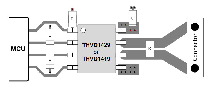
Rather than implementing a complex, costly and space-consuming design with multiple external protection components, the THVD1429 can help to simplify your system. The THVD1429 is a robust RS-485 transceiver that has integrated TVS protection to withstand 2.5 kV of surge. This transceiver is rated to exceed Class 3 (2 kV) of IEC 61000-4-5 without external protection components.
Take a look at the system-level design of the RS-485 communication in Figure 3, this time using an integrated solution instead of the discrete approach shown in Figure 2. Not only does this solution reduce several external protection components, but the industry-standard eight-pin small-outline integrated circuit (SOIC-8) package of the THVD1429 enables a quick and easy way to evaluate and upgrade existing transceivers.
 Figure 3 Integrated Solution with the THVD1429 or THVD1419 (2.5-kV Surge Protection)
In addition to 2.5 kV of integrated surge protection, this RS-485 transceiver family offers several other common types of protection, including 8 kV of contact discharge ESD (IEC 61000-4-2), 4 kV of EFT (IEC 61000-4-4), and 16 kV of human body model ESD. The on-chip protection implementation of these transceivers significantly increases the robustness of the device and end equipment. So, whether your goal is to simplify design complexity or time, reduce board space, simplify the bill of materials or increase the surge protection rating, the THVD1429 RS-485 transceiver family can help ensure that your designs are ready for the great outdoors.
Additional Resources
- View detailed lab data and jitter measurements of the THVD1429 over varying data rates and distances in the application note, “Signal Integrity Versus Data Rate and Cable Length for RS-485 Transceivers.”
- Learn about other types of protection, like EFT, in the TI E2E™ Community blog series, “What is an EFT?”
- Evaluate the THVD1429 or any other TI RS-485 transceiver with our “RS-485 Half Duplex EVM User’s Guide.”
- Looking for isolation for your RS-485 designs? View our portfolio of isolated RS-485 transceivers.