Hybrid Electric Vehicles and Electric Vehicles Need Different Isolated DC/DCs to Win
An hybrid electric vehicle and electric vehicle (HEV/EV) has various subsystems and critical components working together. Isolated DC/DC converters work similar to how players practice a play from the team playbook, each with their own individual assignments for the greater good of the team.
If you’re a football fan, you probably recognize the similarity between Figure 1 and a play diagram. The design choices and play scheme with isolated DC/DC solutions working together can make a difference in the overall performance of the HEV/EV and determine whether it is a winning EV or not.
 Figure 1 A Play Diagram Leading to a Successful Play – AC Input and Battery Reserves Powering HEV/EV Subsystems Using Isolated DC/DC Converters
Several blog posts have described HEV/EV powertrain needs, on-board chargers (OBCs) or EV/pile charging systems discussing AC/DC (using the UCC28070-Q1) and high-power isolated DC/DC systems (using the UCC28951-Q1). Other subsystems in the HEV/EV require isolated DC/DC controllers. Isolation is important for dealing with high voltage safely in electrified vehicles, and automotive specifications call for twice the functional isolation. High voltages in hybrids permit size reductions in the combustion engine, which reduce the power required for motion.
Figure 2 highlights some of the basic subsystems found in an HEV/EV; however, not all HEV/EVs are designed this way. This also includes special-purpose vehicles or vehicles with less than four wheels since they also convert stored battery energy to move.
 Figure 2 HEV/EV Subsystems Requiring Isolated DC/DC Converters
Figure 3 shows an electric bike (e-bike). Special-purpose vehicles would include small task-oriented vehicles (carts, utility task, all-terrain) and personal transportation devices (e-bikes, scooters, wheelchairs, e-rickshaws, even skateboards).
 Figure 3 E-bike Subsystem Requiring Isolated DC/DC Converters
For subsystems that need regulated and isolated voltages to run those electronics that cannot directly connect to the battery voltage, you’ll need to decide on the best topologies for isolated DC/DC subsystems. Think in terms of scripted isolated DC/DC plays that will result in a score from short distances. You need a list of proven designs and their matchups between the output power and choice of topologies.
For example, the engine control unit (ECU) housing the electronics that control and quarterback an HEV/EV will need a lower DC voltage from the 12 V battery bank. A dedicated flyback design based on the UCC28700-Q1 primary-side regulated flyback controller offers the lowest bill of materials (BOM) and design cost given that the power level is under 50 W. An electrified car’s positive temperature coefficient (PTC) heater module may require isolation from the battery voltage and wide voltage range from the battery; a good choice is the UCC2808A-2Q1 in a push-pull topology, which is a dual interleaved pulse-width modulator (PWM) for several hundreds of watts of power. Motors for pumps, compressors, fans or blowers less than 500 W can use a half-bridge controller when the voltage from the 48 V battery banks need isolation and/or voltage regulation.
You could select the LM25037-Q1 and configure the device as a full-bridge topology for loads greater than 500 W. You can use this same controller in a push-pull topology for a Class A/B audio amplifier that uses both a positive and negative voltage rail for the audio power amplifier. The push-pull topology is also a good choice for driving isolated gate bipolar transistors (IGBTs) used in motor drives or inverters needing positive or negative voltage rails for the gate drive.
An active clamp-forward controller also has its place within the HEV/EV automotive power-management architecture for motorcycle or scooter applications. The controller improves the efficiency of hard-switched topologies. You will have to base your choice of topology on power output, efficiency, cost, BOM, design complexity and area for layout, but in an automotive system you also have to think about temperature ranges, environmental conditions, safety and isolation vs. nonisolated, and input and output voltage ranges. Spending more money on the topology choice to achieve better efficiency may eliminate the need for expensive cooling techniques in the car’s thermal design, and possibly lead to lower overall system cost and improved reliability.
For aftermarket solutions – for example, the premium audio market – nonautomotive components can open up the choice of controllers to cover other topologies; for example, using a simple boost topology for a Class-D audio amplifier design. Every coach needs a full roster of players if they want a winning team.
You could consider the advantages of using a single controller in multiple topologies. The UC2825A-Q1 or UC2856-Q1 are both general-purpose pulse-width modulated (PWM) controllers for use in boost, flyback, forward, push-pull, half-bridge and full-bridge designs.
Table 1 is an automotive isolated DC/DC topology game plan showing winning design choices. I included AC/DC power factor correction (PFC) even though the focus of this post was isolated DC/DC conversion.
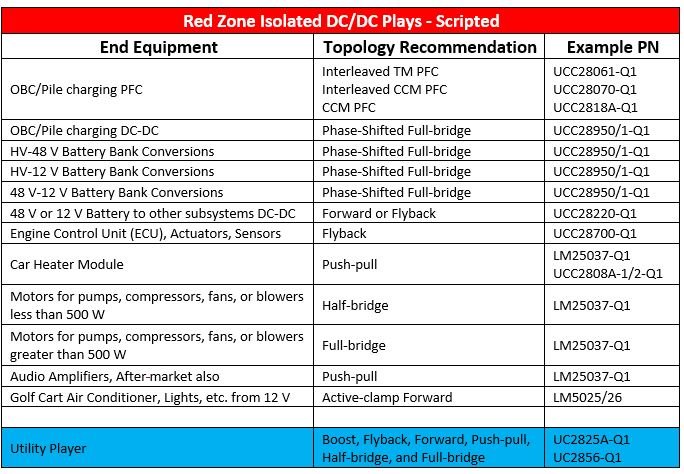
|
Table 2 is another viewpoint of the game plan showing general guidelines for DC-DC topology choices given a power range for the design.

|
What other isolated DC/DC applications do you require in HEV/EV vehicles? Thinking about this topic as a game plan reminds me that I need to check my favorite player stats in preparation for next week’s game.
Learn more about TI’s solutions for hybrid/electric powertrain systems.
IMPORTANT NOTICE AND DISCLAIMER
TI PROVIDES TECHNICAL AND RELIABILITY DATA (INCLUDING DATASHEETS), DESIGN RESOURCES (INCLUDING REFERENCE DESIGNS), APPLICATION OR OTHER DESIGN ADVICE, WEB TOOLS, SAFETY INFORMATION, AND OTHER RESOURCES “AS IS” AND WITH ALL FAULTS, AND DISCLAIMS ALL WARRANTIES, EXPRESS AND IMPLIED, INCLUDING WITHOUT LIMITATION ANY IMPLIED WARRANTIES OF MERCHANTABILITY, FITNESS FOR A PARTICULAR PURPOSE OR NON-INFRINGEMENT OF THIRD PARTY INTELLECTUAL PROPERTY RIGHTS.
These resources are intended for skilled developers designing with TI products. You are solely responsible for (1) selecting the appropriate TI products for your application, (2) designing, validating and testing your application, and (3) ensuring your application meets applicable standards, and any other safety, security, or other requirements. These resources are subject to change without notice. TI grants you permission to use these resources only for development of an application that uses the TI products described in the resource. Other reproduction and display of these resources is prohibited. No license is granted to any other TI intellectual property right or to any third party intellectual property right. TI disclaims responsibility for, and you will fully indemnify TI and its representatives against, any claims, damages, costs, losses, and liabilities arising out of your use of these resources.
TI’s products are provided subject to TI’s Terms of Sale (www.ti.com/legal/termsofsale.html) or other applicable terms available either on ti.com or provided in conjunction with such TI products. TI’s provision of these resources does not expand or otherwise alter TI’s applicable warranties or warranty disclaimers for TI products.
Mailing Address: Texas Instruments, Post Office Box 655303, Dallas, Texas 75265
Copyright © 2023, Texas Instruments Incorporated