-
Five Benefits of Enhanced PWM Rejection for In-line Motor Control
Five Benefits of Enhanced PWM Rejection for In-line Motor Control
Manny Soltero
There’s almost always more than one way to solve a problem. Sometimes the most widely used method doesn’t yield the biggest benefit. System designers working on motor control projects use various current measurement methods to ensure the motor is running efficiently and to prevent possible damage. There are three main methods to measure current in a motor design. In this post, I’ll review these three methods and share the top 5 advantages for in-line motor current sensing using enhanced pulse width modulation (PWM) rejection.
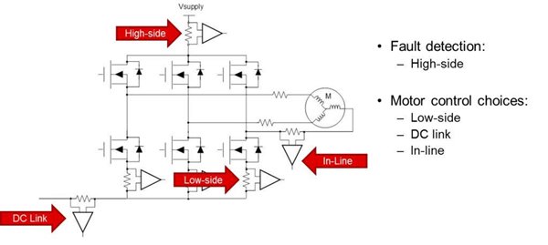
As Figure 1 depicts, there are essentially three different methods to measure current in three-phase motor-drive systems: low-side, DC link and in line. While Figure 1 shows the traditional three-phase PWM inverter needed to drive a DC motor with the three pairs of power MOSFETs (insulated-gate bipolar transistor IGBTs are very common as well), the figure also includes high-side current sensing which is typically used for gross fault conditions such as a short to ground.
 Figure 1 Various Current-sensing
Methods for Three-phase Motor-drive Systems
Figure 1 Various Current-sensing
Methods for Three-phase Motor-drive SystemsMany designers use the first two methods (low side, DC link and various combinations thereof) because standard current-sensing solutions are readily available – typically with fast response times, higher bandwidths, fast output slew rates and low common-mode input voltages. But just because products are available that can sense phase current via low-side or DC link doesn’t mean that these solutions represent the easiest way. The idea behind measuring current in these fashions is to try to replicate the current being driven into the motor windings. This replication effort occurs in software; it can be quite involved and is never truly exact.
The in-line current sensing method seems to be the most logical because that is the current you are ultimately trying to measure, but there is a challenge with this approach. The PWM signals driving the MOSFETs or IGBTs wreak havoc on the current-sense amplifier. The common-mode signals at the sense resistor are driven from the supply voltage to ground with very fast transient switching characteristics, while the current-sense amplifier is trying to measure a small differential signal across the sense resistor itself. Figure 2 is an oscilloscope shot of the sinusoidal phase current (red waveform) generated by the PWM inverter. In this case, the PWM frequency is 100 kilohertz (kHz) sourced by the LMG5200 GaN Half-Bridge Power Stage (more details can be found in the TI Design stated at the bottom). Note the fast switching signals are what the in-line current sense amplifier is subjected to as it measures the phase current. If I can use an analogy, this is like trying to measure the liquid in a cup as it floats along the sea during a hurricane. No wonder most designers use low-side sensing! Until now …
 Figure 2 Measuring Phase Current Amidst
Fast Common-mode Transients
Figure 2 Measuring Phase Current Amidst
Fast Common-mode TransientsBefore describing the potential benefits, let me explain enhanced PWM rejection. Enhanced PWM rejection is active circuitry that forces the output voltage to settle much more quickly than traditional methods. As input common-mode signals with fast transitions are detected by the current-sense amplifier, these disturbances are minimized as they propagate through the device’s output. An alternate method to reduce these disturbances (or affectionately called by designers – “ringing”) is to use high-bandwidth amplifiers (in the MHz range) to settle the output as quickly as possible, but that may be an expensive proposition.
Figure 3 shows the output voltage signal for each of the phases represented without noise introduction. The red waveform is a representation of the signal to show that the power transistors, which are electronically commutated, replicate as close as possible a sinusoidal waveform to the motor. The current-sense amplifier will experience an input common-mode voltage signal from the power-supply rail (VBATT = 48V, for example) to ground.
 Figure 3 Expected Voltage Waveform Due
to Enhanced PWM Rejection
Figure 3 Expected Voltage Waveform Due
to Enhanced PWM RejectionBenefit #1: Reduced Blanking Time
Common-mode PWM transient suppression allows for less “ringing” at the output of the current-sense amplifier. Having to wait for the voltage signal to settle is a major drawback, especially for systems that require low duty cycles (≤10%) because the time to take the current measurement is shortened (commonly known in the industry as blanking time).
Benefit #2: In-line Current Sensing
Coupled with a high common-mode input voltage, enhanced PWM rejection allows for the ability to monitor current in line. As discussed previously, the robustness of the current-sense amplifier is a necessity due to the harsh environment to which it’s exposed. Aside from this requirement, the amplifier must also have high AC and DC accuracy to provide system designers the precise current sensor measurements you can read more about in-line motor current sensing using the INA240 in Low-Drift, Precision, In-Line Motor Current Measurements With PWM Rejection.
Benefit #3: Possible Elimination of Galvanic Isolation
Another benefit from enhanced PWM rejection is subtle but important. With enhanced PWM rejection, designers may be able to eliminate the use of an isolated current-sensing device when galvanic isolation is not part of the system requirements. Customers often use isolated devices to decouple the noise generated as the PWM signals travel through the sense resistor. This decoupling is no longer needed with enhanced PWM rejection.
Benefit #4: Algorithm Optimization
I alluded to this benefit earlier – algorithm optimization. With enhanced PWM rejection, the need to replicate or calculate the phase current is no longer an issue because the answer is already provided directly. Only minimal software is required to run the motor efficiently.
Benefit #5: Increased Motor Efficiency
Finally, I get to last benefit, which arguably matters most to designers – increased motor efficiency. Motor manufacturers and motor-drive system designers are always looking for ways to improve efficiency in the motor. High AC and DC accuracy, fast output response and reduced blanking time enable motor operation at the highest efficiency possible. Precise timing control of the multiphase motor reduces the blanking time as much as possible, which in turn maximizes motor efficiency.
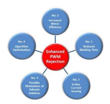
Figure 4 shows the five benefits.
 Figure 4 Five Benefits of Enhanced PWM
Rejection
Figure 4 Five Benefits of Enhanced PWM
RejectionThe INA240 current-sense amplifier from Texas Instruments incorporates enhanced PWM rejection which brings with it a wealth of system-level benefits to your motor design. See Current-sensing solutions for more information about the INA240 and other current sense amplifiers.
Additional Resources
- Download the INA240 data sheet.
- Order the INA240 evaluation module (EVM).
- Check out the TI Design 48-V 10-A In-Line Three-Phase High-Frequency Gallium Nitride (GaN) Inverter for Brushless Motors Reference Design.
- Read the application note, “Current Sensing for In-Line Motor Control Applications.”
- Read these new TI TechNotes to learn more use cases for in-line motor and solenoid control
IMPORTANT NOTICE AND DISCLAIMER
TI PROVIDES TECHNICAL AND RELIABILITY DATA (INCLUDING DATASHEETS), DESIGN RESOURCES (INCLUDING REFERENCE DESIGNS), APPLICATION OR OTHER DESIGN ADVICE, WEB TOOLS, SAFETY INFORMATION, AND OTHER RESOURCES “AS IS” AND WITH ALL FAULTS, AND DISCLAIMS ALL WARRANTIES, EXPRESS AND IMPLIED, INCLUDING WITHOUT LIMITATION ANY IMPLIED WARRANTIES OF MERCHANTABILITY, FITNESS FOR A PARTICULAR PURPOSE OR NON-INFRINGEMENT OF THIRD PARTY INTELLECTUAL PROPERTY RIGHTS.
These resources are intended for skilled developers designing with TI products. You are solely responsible for (1) selecting the appropriate TI products for your application, (2) designing, validating and testing your application, and (3) ensuring your application meets applicable standards, and any other safety, security, or other requirements. These resources are subject to change without notice. TI grants you permission to use these resources only for development of an application that uses the TI products described in the resource. Other reproduction and display of these resources is prohibited. No license is granted to any other TI intellectual property right or to any third party intellectual property right. TI disclaims responsibility for, and you will fully indemnify TI and its representatives against, any claims, damages, costs, losses, and liabilities arising out of your use of these resources.
TI’s products are provided subject to TI’s Terms of Sale (www.ti.com/legal/termsofsale.html) or other applicable terms available either on ti.com or provided in conjunction with such TI products. TI’s provision of these resources does not expand or otherwise alter TI’s applicable warranties or warranty disclaimers for TI products.
Mailing Address: Texas Instruments, Post Office Box 655303, Dallas, Texas 75265
Copyright © 2023, Texas Instruments Incorporated