-
How to Create a Dynamic Power Solution for Stepper Motors, Relays and LEDs
How to Create a Dynamic Power Solution for Stepper Motors, Relays and LEDs
Jose Gonzalez Torres
As you can see from my previous blog, my dad has always been a great source of inspiration and knowledge for me. There is one piece of advice that keeps coming back to me: “Measure twice and cut once.” However, as engineers, whenever we are challenged to design a control or power circuit for stepper motors, LEDs and other peripherals, we like to adapt the system to specific rules and conditions. We are essentially measuring twice, but only for that specific set of conditions. Any changes after the fact would only mean additional costs and time for evaluation, which can be a big pain for any project. Or as my dad would say: “You already made your cut, you can’t take it back!”
So what happens when you need a solution for multiple systems or configurations? How can you make sure that you maintain a balance between having a system that can power a motor, but also gives you the flexibility to add other high-voltage devices after your design is done? I recommend starting your design by using a module or subset of the system, which you can later scale.
Interfacing Flexibility
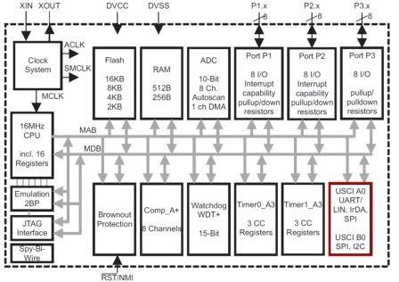
The first thing you have to do is make sure that you can connect your power driver at will. While it is a good idea to choose a host controller with enough general-purpose input/outputs (GPIOs) to drive your outputs, implementing a control scheme or program becomes increasingly difficult, as each GPIO pin has its own call and action to execute. This is where serial interfaces become handy. Most processors have a slew of internal interfaces, as you can see in Figure 1. These interface modules can control memory or external sensors, and even communicate with other processors.
 Figure 1 MSP430™ Internal Block
Diagram
Figure 1 MSP430™ Internal Block
DiagramFor our system, however, the choice is simple. As I mentioned in the intro, we are making this system to drive multiple peripherals including stepper motors. For Stepper motors we need to make sure we supply a sequential and synchronized output from the host.
 Figure 2 SPI Master-slave Connection
Interfaces like Serial Peripheral Interface (SPI) and I2C give you the advantage of having a clock signal coming from the host or master (as shown in Figure 2), with the ability to expand by sharing the serial data and clock lines. For the sake of your design, however, you want to keep costs low, since a solution with a high number of motors and LEDs would need multiple iterations.
Some motors, LEDs and other devices may not benefit from having the internal serial interface as a processor. In those cases, you can employ a serial-to-parallel converter such as the SN74HC595 shown in Figure 3. This device helps channel data sequentially to the outputs. I picked this part for my design because it’s easy to use, low cost, and enables designers to stack or daisy-chain similar devices. Any other serial-to-parallel device can also help complete the task, such as the SN74HC164 or TCA9539.
 Figure 3 SN74HC595
Driving High Voltage and High Current
Unfortunately, you cannot simply drive a high-power load from a host microcontroller. You can, however, apply a FET to lower the overall current demand from the processor. This is in fact one of the more popular threads in design forums, and the main reason why the “Interfacing the 3-V MSP430 to 5-V Circuits” application note is very popular. If you take a page from this app note, you’ll see that the ULN2003A is a simple solution.
Figure 4 showcases how the MSP430 microcontroller and ULN2003A can drive a 12V logic rail along with some motors and LEDs. This works out great because the ULN2003A can handle voltages up to 50V and currents up to 500mA/channel, which gives you ample range for motors and LEDs.
 Figure 4 Connecting the MSP30 to High Voltage and High Current Loads
Putting It All Together
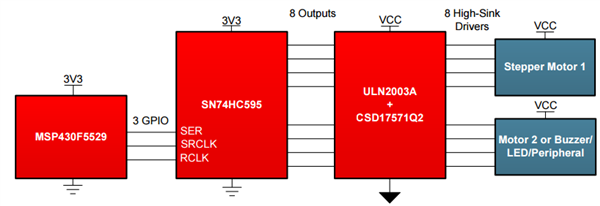
Now that you have everything you need, you can connect your MSP430 MCU, SN74HC595, ULN2003A and a CSD17571Q2 to create a flexible power structure that’s scalable in multiples of eight channels, as shown in Figure 5.
 Figure 5 Our Dynamic Driver
System
Figure 5 Our Dynamic Driver
SystemYou can use this architecture to create complex systems such as an air conditioner, an LED display matrix, or even a robot with multiple lights and motors. You can also create multiple versions of the same design with added features or functionality, such as extra displays or motors, as shown in Figure 6.
 Figure 6 Scaling Our Power Driver to
Accommodate More Peripherals
Figure 6 Scaling Our Power Driver to
Accommodate More PeripheralsBecause you kept the design at a comfortable scale, you can now expand or reduce your features based on your application requirements, or recycle the same structure to come up with other applications that need high voltage, high current or both. And because you only chose the lower-cost alternatives, you can ensure that your board remains cost-effective, even with multiple iterations.
This is such an easy-to-use and flexible design, that we took this idea and made a BoosterPack out of it. But it is just one of the many different ways that you can drive high-power peripherals such as stepper motors and LEDs. What other architectures can you think of? Please let me know in the comments.
Additional Resources
- Download the Configurable Stepper Driver for HVAC Louver and Motor Control Reference Design.
- Download the design of an Integrated solution for this power driver.
- Learn more about interfacing processors with high voltages.