SBOS700 December 2014 OPA2277-EP
PRODUCTION DATA.
- 1 Features
- 2 Applications
- 3 Description
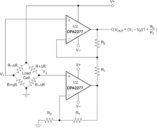
- 4 Load Cell Amplifier Schematic
- 5 Revision History
- 6 Pin Configuration and Functions
- 7 Specifications
- 8 Detailed Description
- 9 Application and Implementation
- 10Power Supply Recommendations
- 11Layout
- 12Device and Documentation Support
- 13Mechanical, Packaging, and Orderable Information
Package Options
Mechanical Data (Package|Pins)
- D|8
Thermal pad, mechanical data (Package|Pins)
Orderable Information
1 Features
- Ultra-Low Offset Voltage: 10 µV
- High Open-Loop Gain: 134 dB
- High Common-Mode Rejection: 140 dB
- High Power Supply Rejection: 130 dB
- Low Bias Current: 1-nA Maximum
- Wide Supply Range: ±2 to ±18 V
- Low Quiescent Current: 800 µA/Amplifier
- Supports Defense, Aerospace, and Medical Applications
- Controlled Baseline
- One Assembly and Test Site
- One Fabrication Site
- Available in Military (–55°C to 125°C) Temperature Range (1)
- Extended Product Life Cycle
- Extended Product-Change Notification
- Product Traceability
2 Applications
- Transducer Amplifier
- Bridge Amplifier
- Temperature Measurements
- Strain Gage Amplifier
- Precision Integrator
- Battery-Powered Instruments
- Test Equipment
3 Description
The OPA2277 precision operational amplifier replaces the industry standard OP-177. It offers improved noise, wider output voltage swing, and is twice as fast with half the quiescent current. Features include ultra-low offset voltage and drift, low bias current, high common-mode rejection, and high power supply rejection.
OPA2277 operates from ±2-V to ±18-V supplies with excellent performance. Unlike most operational amplifiers, which are specified at only one supply voltage, the OPA2277 is specified for real-world applications; a single limit applies over the ±5-V to ±15-V supply range. High performance is maintained as the amplifiers swing to their specified limit. Because the initial offset voltage (±20 μV max) is so low, user adjustment is usually not required.
OPA2277 is easy to use and free from phase inversion and overload problems found in some operational amplifiers. It is stable in unity gain and provides excellent dynamic behavior over a wide range of load conditions. OPA2277 features completely independent circuitry for lowest crosstalk and freedom from interaction, even when overdriven or overloaded. Dual versions are available in DIP-8, SO-8. OPA2277 is fully specified and operates from –55°C to 125°C.
Device Information(1)
| ORDER NUMBER | PACKAGE | BODY SIZE (NOM) |
|---|---|---|
| OPA2277MDTEP | SOIC (8) | 3.91 mm × 4.90 mm |
- For all available packages, see the orderable addendum at the end of the data sheet.
4 Load Cell Amplifier Schematic
