SLVSDW6C April 2017 – April 2021 TPS7H1101A-SP
PRODUCTION DATA
- 1 Features
- 2 Applications
- 3 Description
- 4 Revision History
- 5 Pin Configuration and Functions
- 6 Specifications
- 7 Detailed Description
- 8 Application and Implementation
- 9 Power Supply Recommendations
- 10Layout
- 11Device and Documentation Support
- 12Mechanical, Packaging, and Orderable Information
Package Options
Mechanical Data (Package|Pins)
- HKR|16
- KGD|0
Thermal pad, mechanical data (Package|Pins)
Orderable Information
8.2.1.2 PCL
PCL resistor, RPCL, sets the overcurrent limit activation point and can be calculated per Equation 3.
where
- VREF = 0.605 V
- ICL = Programmable current limit (A)
- Current sense ratio (CSR) is the ratio of output load current to ICS; typical value of the CSR is 52000
- Offset value 0.0403 is a fixed offset derived from internal keep-alive biasing
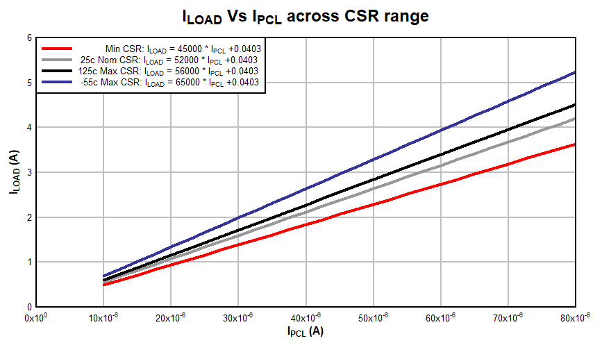
Figure 8-3 shows the output load current (ILOAD) versus PCL terminal current (IPCL) varied with minimum and maximum range of CSR values by temperature. The RPCL resistor should be chosen to set the worst case ILOAD across system normal operating load and temperature range without reaching overcurrent activation point of IPCL · RPCL ≥ VREF.
Additionally, a suitable resistor RCS must be chosen to ensure the CS terminal is within its operating range of 0.3 V to VIN and VCS needs to be greater than 0.9 · VREF (0.544 V) to insure foldback remains enabled when current activation point is triggered.
The maximum PCL is 3.5 A. The range of resistor that can be used on the PCL terminal to GND is 8.2 kΩ to 160 kΩ. It is not recommended to use overcurrent limit activation thresholds of less than 500 mA due to internal bias offset currents representing a larger percentage of total IPCLcurrent and therefore additional error.
 Figure 8-3 ILOAD (A) vs IPCL (A)