SLUS515G September 2002 – December 2015 UCC28050 , UCC28051 , UCC38050 , UCC38051
PRODUCTION DATA.
- 1 Features
- 2 Applications
- 3 Description
- 4 Revision History
- 5 Pin Configuration and Functions
- 6 Specifications
- 7 Detailed Description
- 8 Application and Implementation
- 9 Power Supply Recommendations
- 10Layout
- 11Device and Documentation Support
- 12Mechanical, Packaging, and Orderable Information
Package Options
Refer to the PDF data sheet for device specific package drawings
Mechanical Data (Package|Pins)
- D|8
- P|8
Thermal pad, mechanical data (Package|Pins)
Orderable Information
10 Layout
10.1 Layout Guidelines
10.1.1 Bias Current
The bias voltage is supplied by a bias winding on the inductor. Select the turns ratio so that sufficient bias voltage can be achieved at low AC line voltage. The bias capacitor must be large enough to maintain sufficient voltage with AC line variations. Connect a 0.1-μF bypass capacitor between the VCC pin and the GND pin as close to the integrated circuit as possible. For wide line variations, a resistor, RB, is necessary to permit clamping action. The bias voltage should also be clamped with an external zener diode to a maximum of 18 V.
10.1.2 Zero Current Detection
The zero current detection activates when the ZCD voltage falls below 1.4 V. The bias winding can provide the necessary voltage. This pin has a clamp at approximately 5 V. Add a current limiting resistor, RZC, to keep the maximum current below 1 mA.
10.2 Layout Example
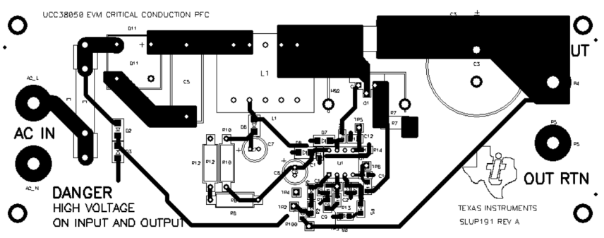
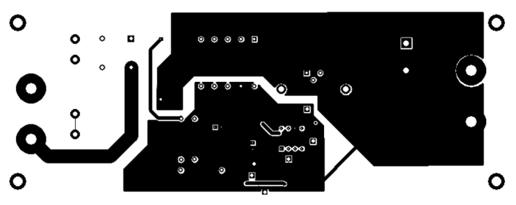
 Figure 24. UCC38050 Layout Example
