JAJSAQ5F December 2007 – October 2016 DAC121C081 , DAC121C085
PRODUCTION DATA.
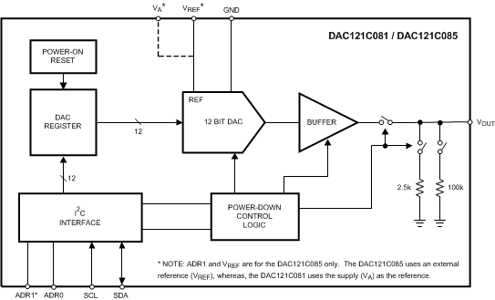
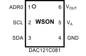
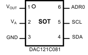
DAC121C081は12ビット、シングル・チャネル、電圧出力のD/Aコンバータ(DAC)で、2.7V~5.5Vの電源で動作します。出力アンプではレール・ツー・レールの出力が可能で、セトリング時間は8.5µsです。DAC121C081は電源電圧を基準として使い、最も広い動的出力範囲を提供します。5Vでの動作時、消費電流は通常値で132µAです。6ピンのSOTおよびWSONパッケージで供給され、3つのアドレス・オプションをピンにより選択できます。
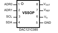
代替品として、DAC121C085は9つのI2Cアドレシング・オプションがあり、外部基準電圧を使用します。性能やセトリング時間はDAC121C081と同じで、8リードのVSSOPで供給されます。
型番 | パッケージ | 本体サイズ(公称) |
---|---|---|
DAC121C081 | WSON (6) | 2.20mm×2.50mm |
SOT (6) | 1.60mm×2.90mm | |
DAC121C085 | VSSOP (8) | 3.00mm×3.00mm |
Changes from E Revision (January 2016) to F Revision
Changes from D Revision (March 2013) to E Revision
Changes from C Revision (March 2013) to D Revision
DAC121C081およびDAC121C085で使用する2線式のI2C互換シリアル・インターフェイスは、High-Speedモード(3.4MHz)も含む3つの速度モードすべてで動作します。外部アドレス選択ピンにより、2線式バスごとに3つまでのDAC121C081、または9つまでのDAC121C085デバイスを使用できます。DAC121C081には、追加のアドレス・オプションを使用できるピン互換の代替品もあります。
DAC121C081およびDAC121C085には16ビットのレジスタが内蔵されており、動作モード、パワーダウン条件、出力電圧を制御できます。パワー・オン・リセット回路により、0VまでのDAC出力電力が保証されます。パワーダウン機能により、消費電力は1マイクロワット未満まで減少します。低消費電力と小型のパッケージから、これらのDACはバッテリ駆動の機器で使用するための非常に優れた選択肢です。各DACは、拡張産業用温度範囲の-40℃~+125℃で動作します。
DAC121C081およびDAC121C085は、どちらもピン互換なDACファミリの一部であり、このファミリには分解能が8および10ビットの製品も含まれています。8ビットDACについては、DAC081C081とDAC081C085を参照してください。10ビットDACについては、DAC101C081とDAC101C085を参照してください。
PIN | TYPE | DESCRIPTION | EQUIVALENT CIRCUIT | |||
---|---|---|---|---|---|---|
NAME | WSON | SOT | VSSOP | |||
ADR0 | 1 | 6 | 1 | Digital Input, three levels |
Tri-state Address Selection Input. Sets the two Least Significant Bits (A1 and A0) of the 7-bit slave address. (see Table 1) |
![]() |
ADR1 | — | — | 2 | Digital Input, three levels |
Tri-state Address Selection Input. Sets Bits A6 and A3 of the 7-bit slave address. (see Table 1) | |
GND | 4 | 3 | 5 | Ground | Ground for all on-chip circuitry | — |
SCL | 2 | 5 | 3 | Digital Input | Serial Clock Input. SCL is used together with SDA to control the transfer of data in and out of the device. |
![]() |
SDA | 3 | 4 | 4 | Digital Input/Output |
Serial Data bi-directional connection. Data is clocked into or out of the internal 16-bit register relative to the clock edges of SCL. This is an open-drain data line that must be pulled to the supply (VA) by an external pullup resistor. | |
VOUT | 6 | 1 | 8 | Analog Output | Analog Output Voltage | — |
VA | 5 | 2 | 6 | Supply | Power supply input. For the SOT and WSON versions, this supply is used as the reference. Must be decoupled to GND. | — |
VREF | — | — | 7 | Supply | Unbufferred reference voltage. For the VSSOP, this supply is used as the reference. VREF must be free of noise and decoupled to GND. | — |
PAD | (LLP only) | — | — | Ground | Exposed die attach pad can be connected to ground or left floating. Soldering the pad to the PCB offers optimal thermal performance and enhances package self-alignment during reflow. | — |
MIN | MAX | UNIT | |||
---|---|---|---|---|---|
Supply voltage, VA | –0.3 | 6.5 | V | ||
Voltage on any input pin | –0.3 | 6.5 | V | ||
Input current at any pin(4) | ±10 | mA | |||
Package input current(4) | ±20 | mA | |||
Power consumption at TA = 25°C | See(5) | ||||
Junction temperature, TJ | 150 | °C | |||
Storage temperature, Tstg | –65 | 150 | °C |
VALUE | UNIT | ||||
---|---|---|---|---|---|
DAC081C081 in NGF Package | |||||
V(ESD) | Electrostatic discharge | Human-body model (HBM), per ANSI/ESDA/JEDEC JS-001 | All pins except 2 and 3 | ±2500 | V |
Pins 2 and 3 | ±5000 | ||||
Charged-device model (CDM), per JEDEC specification JESD22-C101 | All pins except 2 and 3 | ±1000 | |||
Pins 2 and 3 | ±1000 | ||||
Machine model (MM) | All pins except 2 and 3 | ±250 | |||
Pins 2 and 3 | ±350 | ||||
DAC081C081 in DDC Package | |||||
V(ESD) | Electrostatic discharge | Human-body model (HBM), per ANSI/ESDA/JEDEC JS-001 | All pins except 4 and 5 | ±2500 | V |
Pins 4 and 5 | ±5000 | ||||
Charged-device model (CDM), per JEDEC specification JESD22-C101 | All pins except 4 and 5 | ±1000 | |||
Pins 4 and 5 | ±1000 | ||||
Machine model (MM) | All pins except 4 and 5 | ±250 | |||
Pins 4 and 5 | ±350 | ||||
DAC081C085 in DGK Package | |||||
V(ESD) | Electrostatic discharge | Human-body model (HBM), per ANSI/ESDA/JEDEC JS-001 | All pins except 3 and 4 | ±2500 | V |
Pins 3 and 4 | ±5000 | ||||
Charged-device model (CDM), per JEDEC specification JESD22-C101 | All pins except 3 and 4 | ±1000 | |||
Pins 3 and 4 | ±1000 | ||||
Machine model (MM) | All pins except 3 and 4 | ±250 | |||
Pins 3 and 4 | ±350 |
MIN | MAX | UNIT | |
---|---|---|---|
Operating temperature, TA | −40 | 125 | °C |
Supply voltage, VA | 2.7 | 5.5 | V |
Reference voltage, VREFIN | 1 | VA | V |
Digital input voltage(2) | 0 | 5.5 | V |
Output load | 0 | 1500 | pF |
THERMAL METRIC(1)(2)(3) | DAC121C081 | DAC121C085 | UNIT | ||
---|---|---|---|---|---|
NGF (WSON) | DDC (SOT) | DGK (VSSOP) | |||
6 PINS | 6 PINS | 8 PINS | |||
RθJA | Junction-to-ambient thermal resistance | 190 | 250 | 240 | °C/W |
PARAMETER | TEST CONDITIONS | MIN | TYP(3) | MAX(3) | UNIT | ||
---|---|---|---|---|---|---|---|
STATIC PERFORMANCE | |||||||
INL | Resolution | 12 | Bits | ||||
Monotonicity | 12 | Bits | |||||
Integral Non-Linearity | 2.2 | 8 | LSB | ||||
–8 | –1.5 | ||||||
DNL | Differential Non-Linearity | 0.18 | 0.6 | LSB | |||
–0.5 | –0.12 | LSB | |||||
ZE | Zero Code Error | IOUT = 0 | 1.1 | 10 | mV | ||
FSE | Full-Scale Error | IOUT = 0 | –0.1 | −0.7 | %FSR | ||
GE | Gain Error | All ones Loaded to DAC register | –0.2 | −0.7 | %FSR | ||
ZCED | Zero Code Error Drift | –20 | µV/°C | ||||
TC GE | Gain Error Tempco | VA = 3 V | –0.7 | ppm FSR/°C | |||
VA = 5 V | –1 | ||||||
ANALOG OUTPUT CHARACTERISTICS (VOUT) | |||||||
Output voltage range(4) | DAC121C085 | 0 | VREF | V | |||
DAC121C081 | 0 | VA | |||||
ZCO | Zero code output | VA = 3 V, IOUT = 200 µA | 1.3 | mV | |||
VA = 5 V, IOUT = 200 µA | 7 | ||||||
FSO | Full scale output | VA = 3 V, IOUT = 200 µA | 2.984 | V | |||
VA = 5 V, IOUT = 200 µA | 4.989 | ||||||
IOS | Output short-circuit current (ISOURCE) |
VA = 3 V, VOUT = 0 V, Input Code = FFFh. |
56 | mA | |||
VA = 5 V, VOUT = 0 V, Input Code = FFFh. |
69 | ||||||
IOS | Output short-circuit current (ISINK) |
VA = 3 V, VOUT = 3 V, Input Code = 000h. |
–52 | mA | |||
VA = 5 V, VOUT = 5 V, Input Code = 000h. |
–75 | ||||||
IO | Continuous output current(4) | Available on the DAC output | 11 | mA | |||
CL | Maximum load capacitance | RL = ∞ | 1500 | pF | |||
RL = 2 kΩ | 1500 | ||||||
ZOUT | DC output impedance | 7.5 | Ω | ||||
REFERENCE INPUT CHARACTERISTICS (DAC121C085 only) | |||||||
VREF | Input range minimum | 1 | 0.2 | V | |||
Input range maximum | VA | V | |||||
Input impedance | 120 | kΩ | |||||
LOGIC INPUT CHARACTERISTICS (SCL, SDA) | |||||||
VIH | Input high voltage | 0.7 × VA | V | ||||
VIL | Input low voltage | 0.3 × VA | V | ||||
IIN | Input current | ±1 | µA | ||||
CIN | Input pin capacitance(4) | 3 | pF | ||||
VHYST | Input hysteresis | 0.1 × VA | V | ||||
LOGIC INPUT CHARACTERISTICS (ADR0, ADR1) | |||||||
VIH | Input high voltage | VA- 0.5 | V | ||||
VIL | Input low voltage | 0.5 | V | ||||
IIN | Input current | ±1 | µA | ||||
LOGIC OUTPUT CHARACTERISTICS (SDA) | |||||||
VOL | Output low voltage | ISINK = 3 mA | 0.4 | V | |||
ISINK = 6 mA | 0.6 | ||||||
IOZ | High-impedence output leakage current | ±1 | µA | ||||
POWER REQUIREMENTS | |||||||
VA | Supply voltage minimum | 2.7 | V | ||||
Supply voltage maximum | 5.5 | ||||||
Normal -- VOUT set to midscale. 2-wire interface quiet (SCL = SDA = VA). (output unloaded) | |||||||
IST_VA-1 | VADAC121C081 supply current | VA = 2.7 V to 3.6 V | 105 | 156 | µA | ||
VA = 4.5 V to 5.5 V | 132 | 214 | |||||
IST_VA-5 | VADAC121C085 supply current | VA = 2.7 V to 3.6 V | 86 | 118 | µA | ||
VA = 4.5 V to 5.5 V | 98 | 152 | |||||
IST_VREF | VREF supply current (DAC121C085 only) |
VA = 2.7 V to 3.6 V | 37 | 43 | µA | ||
VA = 4.5 V to 5.5 V | 53 | 61 | |||||
PST | Power consumption (VA and VREF for DAC121C085)(2) |
VA = 3 V | 380 | µW | |||
VA = 5 V | 730 | ||||||
Continuous Operation -- 2-wire interface actively addressing the DAC and writing to the DAC register. (output unloaded) | |||||||
ICO_VA-1 | VADAC121C081 supply current | fSCL=400 kHz | VA = 2.7 V to 3.6 V | 134 | 220 | µA | |
VA = 4.5 V to 5.5 V | 192 | 300 | |||||
fSCL = 3.4 MHz | VA = 2.7 V to 3.6 V | 225 | 320 | µA | |||
VA = 4.5 V to 5.5 V | 374 | 500 | |||||
ICO_VA-5 | VADAC121C085 supply current | fSCL = 400 kHz | VA = 2.7 V to 3.6 V | 101 | 155 | µA | |
VA = 4.5 V to 5.5 V | 142 | 220 | |||||
fSCL = 3.4 MHz | VA = 2.7 V to 3.6 V | 193 | 235 | µA | |||
VA = 4.5 V to 5.5 V | 325 | 410 | |||||
ICO_VREF | VREF supply current (DAC121C085 only) |
VA = 2.7 V to 3.6 V | 33.5 | 55 | µA | ||
VA = 4.5 V to 5.5 V | 49.5 | 71.4 | |||||
PCO | Power consumption (VA and VREF for DAC121C085) |
fSCL = 400 kHz | VA = 3 V | 480 | µW | ||
VA = 5 V | 1.06 | mW | |||||
fSCL = 3.4 MHz | VA = 3 V | 810 | µW | ||||
VA = 5 V | 2.06 | mW | |||||
Power Down -- 2-wire interface quiet (SCL = SDA = VA) after PD mode written to DAC register. (output unloaded) | |||||||
IPD | Supply current (VA and VREF for DAC121C085) |
All power-down modes | VA = 2.7 V to 3.6 | 0.13 | 1.52 | µA | |
VA = 4.5 V to 5.5 V | 0.15 | 3.25 | |||||
PPD | Power consumption (VA and VREF for DAC121C085) |
All power-down modes | VA = 3 V | 0.5 | µW | ||
VA = 5 V | 0.9 |
PARAMETER | TEST CONDITIONS(7) | MIN | TYP(3) | MAX(7)(3) | UNIT | ||
---|---|---|---|---|---|---|---|
ts | Output Voltage Settling Time(4) | 400h to C00h code change RL = 2 kΩ, CL = 200 pF |
6 | 8.5 | µs | ||
SR | Output Slew Rate | 1 | V/µs | ||||
Glitch Impulse | Code change from 800h to 7FFh | 12 | nV-sec | ||||
Digital Feedthrough | 0.5 | nV-sec | |||||
Multiplying Bandwidth(6) | VREF = 2.5 V ± 0.1 Vpp | 160 | kHz | ||||
Total Harmonic Distortion(6) | VREF = 2.5 V ± 0.1 Vpp input frequency = 10 kHz |
70 | dB | ||||
tWU | Wake-Up Time | VA = 3 V | 0.8 | µs | |||
VA = 5 V | 0.5 | µs | |||||
DIGITAL TIMING SPECS (SCL, SDA) | |||||||
fSCL | Serial Clock Frequency | Standard Mode | 100 | kHz | |||
Fast Mode | 400 | ||||||
High Speed Mode, Cb = 100 pF | 3.4 | MHz | |||||
High Speed Mode, Cb = 400 pF | 1.7 | ||||||
tLOW | SCL Low Time | Standard Mode | 4.7 | µs | |||
Fast Mode | 1.3 | ||||||
High Speed Mode, Cb = 100 pF | 160 | ns | |||||
High Speed Mode, Cb = 400 pF | 320 | ||||||
tHIGH | SCL High Time | Standard Mode | 4 | µs | |||
Fast Mode | 0.6 | ||||||
High Speed Mode, Cb = 100 pF | 60 | ns | |||||
High Speed Mode, Cb = 400 pF | 120 | ||||||
tSU;DAT | Data Setup Time | Standard Mode | 250 | ns | |||
Fast Mode | 100 | ||||||
High Speed Mode | 10 | ||||||
tHD;DAT | Data Hold Time | Standard Mode | 0 | 3.45 | µs | ||
Fast Mode | 0 | 0.9 | |||||
High Speed Mode, Cb = 100 pF | 0 | 70 | ns | ||||
High Speed Mode, Cb = 400 pF | 0 | 150 | |||||
tSU;STA | Setup time for a start or a repeated start condition | Standard Mode | 4.7 | µs | |||
Fast Mode | 0.6 | ||||||
High Speed Mode | 160 | ns | |||||
tHD;STA | Hold time for a start or a repeated start condition | Standard Mode | 4 | µs | |||
Fast Mode | 0.6 | ||||||
High Speed Mode | 160 | ns | |||||
tBUF | Bus free time between a stop and start condition | Standard Mode | 4.7 | µs | |||
Fast Mode | 1.3 | ||||||
tSU;STO | Setup time for a stop condition | Standard Mode | 4 | µs | |||
Fast Mode | 0.6 | ||||||
High Speed Mode | 160 | ns | |||||
trDA | Rise time of SDA signal | Standard Mode | 1000 | ns | |||
Fast Mode | 20+0.1Cb | 300 | |||||
High Speed Mode, Cb = 100 pF | 10 | 80 | |||||
High Speed Mode, Cb = 400 pF | 20 | 160 | |||||
tfDA | Fall time of SDA signal | Standard Mode | 250 | ns | |||
Fast Mode | 20+0.1Cb | 250 | |||||
High Speed Mode, Cb = 100 pF | 10 | 80 | |||||
High Speed Mode, Cb = 400 pF | 20 | 160 | |||||
trCL | Rise time of SCL signal | Standard Mode | 1000 | ns | |||
Fast Mode | 20+0.1Cb | 300 | |||||
High Speed Mode, Cb = 100 pF | 10 | 40 | |||||
High Speed Mode, Cb = 400 pF | 20 | 80 | |||||
trCL1 | Rise time of SCL signal after a repeated start condition and after an acknowledge bit. | Standard Mode | 1000 | ns | |||
Fast Mode | 20+0.1Cb | 300 | |||||
High Speed Mode, Cb = 100 pF | 10 | 80 | |||||
High Speed Mode, Cb = 400 pF | 20 | 160 | |||||
tfCL | Fall time of a SCL signal | Standard Mode | 300 | ns | |||
Fast Mode | 20+0.1Cb | 300 | |||||
High Speed Mode, Cb = 100 pF | 10 | 40 | |||||
High Speed Mode, Cb = 400 pF | 20 | 80 | |||||
Cb | Capacitive load for each bus line (SCL and SDA) | 400 | pF | ||||
tSP | Pulse Width of spike suppressed(5)(4) | Fast Mode | 50 | ns | |||
High Speed Mode | 10 | ||||||
toutz | SDA output delay (see the Additional Timing Information section) | Fast Mode | 87 | 270 | ns | ||
High Speed Mode | 38 | 60 |
The DAC121C081 is fabricated on a CMOS process with an architecture that consists of switches and resistor strings that are followed by an output buffer.
For simplicity, a single resistor string is shown in Figure 20. This string consists of 4096 equal valued resistors with a switch at each junction of two resistors, plus a switch to ground. The code loaded into the DAC register determines which switch is closed, connecting the proper node to the amplifier. The input coding is straight binary with an ideal output voltage of:
where
D can take on any integer value from 0 to 4095. This configuration ensures that the DAC is monotonic.
The output amplifier is rail-to-rail, providing an output voltage range of 0 V to VA when the reference is VA. All amplifiers, even rail-to-rail types, exhibit a loss of linearity as the output approaches the supply rails (0 V and VA, in this case). For this reason, linearity is specified over less than the full output range of the DAC. However, if the reference is less than VA, there is only a loss in linearity in the lowest codes. The output capabilities of the amplifier are described in the Electrical Characteristics.
The output amplifiers are capable of driving a load of 2 kΩ in parallel with 1500 pF to ground or to VA. The zero-code and full-scale outputs for given load currents are available in the Electrical Characteristics.
The DAC121C081 uses the supply (VA) as the reference. With that said, VA must be treated as a reference. The analog output is only as clean as the reference (VA). TI recommends driving the reference with a voltage source with low-output impedance.
The DAC121C085 comes with an external reference supply pin (VREF). For the DAC121C085, it is important that VREF be kept as clean as possible.
Applications Information describes a handful of ways to drive the reference appropriately. See Using References as Power Supplies for details.
The I2C-compatible interface operates in all three speed modes. Standard mode (100 kHz) and Fast mode (400 kHz) are functionally the same and will be referred to as Standard-Fast mode in this document. High-Speed mode (3.4MHz) is an extension of Standard-Fast mode and will be referred to as Hs-mode in this document. The following diagrams describe the timing relationships of the clock (SCL) and data (SDA) signals. Pullup resistors or current sources are required on the SCL and SDA busses to pull them high when they are not being driven low. A logic zero is transmitted by driving the output low. A logic high is transmitted by releasing the output and allowing it to be pulled up externally. The appropriate pullup resistor values depends on the total bus capacitance and operating speed.
The I2C interface is bi-directional and allows multiple devices to operate on the same bus. To facilitate this bus configuration, each device has a unique hardware address which is referred to as the slave address. To communicate with a particular device on the bus, the controller (master) sends the slave address and listens for a response from the slave. This response is referred to as an acknowledge bit. If a slave on the bus is addressed correctly, it Acknowledges (ACKs) the master by driving the SDA bus low. If the address doesn't match a device's slave address, it Not-acknowledges (NACKs) the master by letting SDA be pulled high. ACKs also occur on the bus when data is being transmitted. When the master is writing data, the slave ACKs after every data byte is successfully received. When the master is reading data, the master ACKs after every data byte is received to let the slave know it wants to receive another data byte. When the master wants to stop reading, it NACKs after the last data byte and creates a Stop condition on the bus.
All communication on the bus begins with either a Start condition or a Repeated Start condition. The protocol for starting the bus varies between Standard-Fast mode and Hs-mode. In Standard-Fast mode, the master generates a Start condition by driving SDA from high to low while SCL is high. In Hs-mode, starting the bus is more complicated. See High-Speed (Hs) Mode for the full details of a Hs-mode Start condition. A Repeated Start is generated to either address a different device, or switch between read and write modes. The master generates a Repeated Start condition by driving SDA low while SCL is high. Following the Repeated Start, the master sends out the slave address and a read/write bit as shown in Figure 21. The bus continues to operate in the same speed mode as before the Repeated Start condition.
All communication on the bus ends with a Stop condition. In either Standard-Fast mode or Hs-Mode, a Stop condition occurs when SDA is pulled from low to high while SCL is high. After a Stop condition, the bus remains idle until a master generates a Start condition.
See the Phillips I2C® Specification (Version 2.1 Jan, 2000) for a detailed description of the serial interface.
In Standard-Fast mode, the master generates a start condition by driving SDA from high to low while SCL is high. The Start condition is always followed by a 7-bit slave address and a Read/Write bit. After these eight bits have been transmitted by the master, SDA is released by the master and the DAC121C081 either ACKs or NACKs the address. If the slave address matches, the DAC121C081 ACKs the master. If the address doesn't match, the DAC121C081 NACKs the master.
For a write operation, the master follows the ACK by sending the upper eight data bits to the DAC121C081. Then the DAC121C081 ACKs the transfer by driving SDA low. Next, the lower eight data bits are sent by the master. The DAC121C081 then ACKs the transfer. At this point, the DAC output updates to reflect the contents of the 16-bit DAC register. Next, the master either sends another pair of data bytes, generates a Stop condition to end communication, or generates a Repeated Start condition to communicate with another device on the bus.
For a read operation, the DAC121C081 sends out the upper eight data bits of the DAC register. This is followed by an ACK by the master. Next, the lower eight data bits of the DAC register are sent to the master. The master then produces a NACK by letting SDA be pulled high. The NACK is followed by a master-generated Stop condition to end communication on the bus, or a Repeated Start to communicate with another device on the bus.
For Hs-mode, the sequence of events to begin communication differ slightly from Standard-Fast mode. Figure 22 describes this in further detail. Initially, the bus begins running in Standard-Fast mode. The master generates a Start condition and sends the 8-bit Hs master code (00001XXX) to the DAC121C081. Next, the DAC121C081 responds with a NACK. Once the SCL line has been pulled to a high level, the master switches to Hs-mode by increasing the bus speed and generating a Repeated Start condition (driving SDA low while SCL is pulled high). At this point, the master sends the slave address to the DAC121C081, and communication continues as shown in Figure 21.
When the master generates a Repeated Start condition while in Hs-mode, the bus stays in Hs-mode awaiting the slave address from the master. The bus continues to run in Hs-mode until a Stop condition is generated by the master. When the master generates a Stop condition on the bus, the bus must be started in Standard-Fast mode again before increasing the bus speed and switching to Hs-mode. ns16705
The DAC has a seven-bit I2C slave address. For the VSSOP version of the DAC, this address is configured by the ADR0 and ADR1 address selection inputs. For the DAC121C081, the address is configured by the ADR0 address selection input. ADR0 and ADR1 can be grounded, left floating, or tied to VA. If desired, the address selection inputs can be set to VA/2 rather than left floating. The state of these inputs sets the address the DAC responds to on the I2C bus (see Table 1). In addition to the selectable slave address, there is also a broadcast address (1001000) for all DAC121C081's and DAC121C085's on the 2-wire bus. When the bus is addressed by the broadcast address, all the DAC121C081's and DAC121C085's will respond and update synchronously. Figure 24 and Figure 25 describe how the master device should address the DAC through the I2C-Compatible interface.
Keep in mind that the address selection inputs (ADR0 and ADR1) are only sampled until the DAC is correctly addressed with a non-broadcast address. At this point, the ADR0 and ADR1 inputs TRI-STATE and the slave address is locked. Changes to ADR0 and ADR1 will not update the selected slave address until the device is power-cycled.
Slave Address
[A6 - A0] |
DAC121C085 (VSSOP) | DAC121C081 (SOT AND WSON)(1) | Do Not Use(2) | |
---|---|---|---|---|
ADR1 | ADR0 | ADR0 | ||
0001100 | Floating | Floating | Floating | 1000110 |
0001101 | Floating | GND | GND | 1000110 |
0001110 | Floating | VA | VA | 1000111 |
0001000 | GND | Floating | --------------- | 1000100 |
0001001 | GND | GND | --------------- | 1000100 |
0001010 | GND | VA | --------------- | 1000101 |
1001100 | VA | Floating | --------------- | 1100110 |
1001101 | VA | GND | --------------- | 1100110 |
1001110 | VA | VA | --------------- | 1100111 |
1001000 | --------------- Broadcast Address --------------- | 1100100 |
The power-on reset circuit controls the output voltage of the DAC during power up. Upon application of power, the DAC register is filled with zeros and the output voltage is 0 V. The output remains at 0 V until a valid write sequence is made to the DAC.
When resetting the device, it is crutial that the VA supply be lowered to a maximum of 200 mV before the supply is raised again to power up the device. Dropping the supply to within 200 mV of GND during a reset will ensure the ADC performs as specified.
The broadcast address allows the I2C master to write a single word to multiple DACs simultaneously. Provided that all of the DACs exist on a single I2C bus, every DAC updates when the broadcast address is used to address the bus. This feature allows the master to reset all of the DACs on a shared I2C bus to a specific digital code. For instance, if the master writes a power-down code to the bus with the broadcast address, all of the DACs powers down simultaneously.
The toutz specification is provided to aid the design of the I2C bus. After the SCL bus is driven low by the I2C master, the SDA bus will be held for a short time by the DAC121C081. This time is referred to as toutz. The following figure illustrates the relationship between the fall of SCL, at the 30% threshold, to the time when the DAC begins to transition the SDA bus. The toutz specification only applies when the DAC is in control of the SDA bus. The DAC is only in control of the bus during an ACK by the DAC121C081 or a data byte read from the DAC (see Figure 25).
The toutz specification is typically 87 ns in Standard-Fast Mode and 38 ns in Hs-Mode.
The DAC121C081 has three power-down modes. In power-down mode, the supply current drops to 0.13 µA at 3 V and 0.15 µA at 5 V (typical). The DAC121C081 is put into power-down mode by writing a one to PD1 and/or PD0. The outputs can be set to high impedance, terminated by 2.5 kΩ to GND, or terminated by 100 kΩ to GND (see Figure 26).
The bias generator, output amplifier, resistor string, and other linear circuitry are all shut down in any of the power-down modes. When the DAC121C081 is powered down, the value written to the DAC register, including the power-down bits, is saved. While the DAC is in power-down, the saved DAC register contents can be read back. When the DAC is brought out of power-down mode, the DAC register contents will be overwritten and VOUT will be updated with the new 12-bit data value.
The time to exit power-down (Wake-Up Time) is typically 0.8 µs at 3 V and 0.5 µs at 5 V.
To write to the DAC, the master addresses the part with the correct slave address (A6-A0) and writes a zero to the read/write bit. If addressed correctly, the DAC returns an ACK to the master. The master then sends out the upper data byte. The DAC responds by sending an ACK to the master. Next, the master sends the lower data byte to the DAC. The DAC responds by sending an ACK again. At this point, the master either sends the upper byte of the next data word to be converted by the DAC, generates a Stop condition to end communication, or generates a Repeated Start condition to begin communication with another device on the bus. Until generating a Stop condition, the master can continuously write the upper and lower data bytes to the DAC register. This allows for a maximum DAC conversion rate of 188.9 kilo-conversions per second in Hs-mode.
To read from the DAC register, the master addresses the part with the correct slave address (A6-A0) and writes a one to the read/write bit. If addressed correctly, the DAC returns an ACK to the master. Next, the DAC sends out the upper data byte. The master responds by sending an ACK to the DAC to indicate that it wants to receive another data byte. Then the DAC sends the lower data byte to the master. Assuming only one 16-bit data word is read, the master sends a NACK after receiving the lower data byte. At this point, the master either generates a Stop condition to end communication, or a Repeated Start condition to begin communication with another device on the bus.
The DAC register, Figure 26, has sixteen bits. The first two bits are always zero. The next two bits determine the mode of operation (normal mode or one of three power-down modes). The final twelve bits of the shift register are the data bits. The data format is straight binary (MSB first, LSB last), with twelve 0s corresponding to an output of 0 V and twelve 1s corresponding to a full-scale output of VA – 1 LSB. When writing to the DAC Register, VOUT will update on the rising edge of the ACK following the lower data byte.